sandbox/ghigo/src/myembed.h
- Embedded
boundaries
- Utility functions for the geometry of embedded boundaries
- Boundary conditions
- Operator overloading
- Embedded face gradient of a scalar - Dirichlet and Neumann boundary conditions
- Viscous flux through the discrete rigid boundary in a cut-cell
- Extrapolation of a cell-centered scalar - Emerged cells
- Surface force and torque and vorticity
- Prolongation for the multigrid solver
- Lifting the “small cell” CFL restriction
- Default settings
- References
- See also
Embedded boundaries
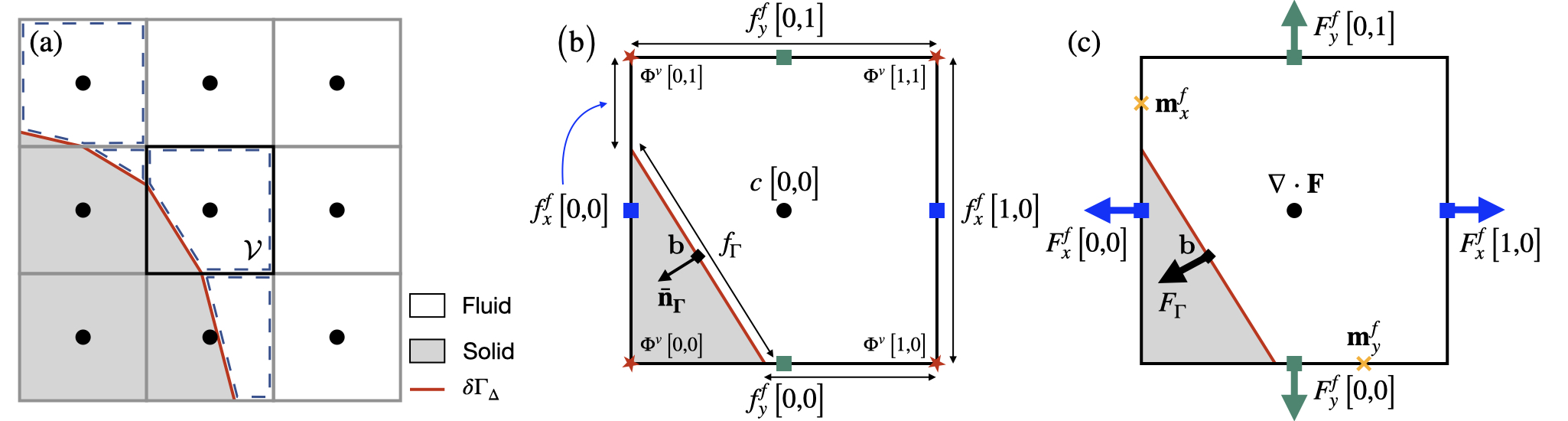
The Cartesian grid embedded boundary method is constructed starting from a uniform Cartesian grid (or a tree grid) \Omega_\Delta and a user-defined distance function \Phi describing the location and shape of the rigid boundary \delta \Gamma of a rigid body \Gamma. Using a distance function guarantees a topologically and analytically coherent representation of the rigid boundary \delta \Gamma, especially when importing the geometry from a possibly faulty .stl file for example.
A discrete piece-wise continuous representation of the rigid boundary, denoted \delta \Gamma_{\Delta}, is then embedded in the grid \Omega_{\Delta} and intersects underlying cells to form irregular fluid control volumes, denoted \mathcal{V}. In each cell cut by the boundary (or cut-cell), the discrete rigid boundary \delta \Gamma_{\Delta} satisfies the following equation for a line (a plane in 3D): \mathbf{\bar{n}}_{\Gamma}\cdot \mathbf{x} = \alpha, where \mathbf{\bar{n}}_{\Gamma} is the inward unit normal vector to the discrete rigid boundary and \alpha is the intercept.
Using the distance function \Phi sampled on the vertices of each cell of grid \Omega_{\Delta}, we then compute the geometric quantities \mathbf{\bar{n}}_{\Gamma} and \alpha in each cut-cell. In the following, interpolations (for Dirichlet boundary conditions for example) assume that the current cell has access to a 5x5 stencil.
#include "fractions.h"
#define BGHOSTS 2
#define EMBED 1
Using the geometric quantities \mathbf{\bar{n}}_{\Gamma} and \alpha in each cut-cell, the geometry of the irregular fluid control volume \mathcal{V} is then characterized by the following Volume-of-Fluid (VOF) quantities, also referred to as the embedded fractions. The volume and area fractions are stored in the fields cs and fs. We also store the volume fraction at the previous time iteration in the field csm1. This is a useful quantity to characterize the volume change in a fluid cell if the discrete rigid boundary \delta \Gamma_{\Delta} is moving.
scalar cs[], csm1[];
face vector fs[];
We define a boolean to determine if emerged cells have been updated or not. This is usefull to avoid using values from emerged cells that have not yet been updated, in particular when performing restriction and refinement operations.
bool emerged = true;Finally, embedded boundary operators specific to trees (prolongation/restriction of embedded fractions, scalars and face vectors) are necessary to allow the Cartesian grid embedded boundary method to be identically apllied to a uniform Cartesian grid and a tree grid. They are defined in the following file.
#if TREE
# include "myembed-tree-moving.h"
#endif
Utility functions for the geometry of embedded boundaries
For a cell containing a fragment of embedded boundary (i.e. for which 0 < cs < 1), embed_geometry() returns the area fraction f_{\Gamma} of, the relative position b of the barycenter (with respect to the center of the cell) of and the inward (pointing from fluid to solid) unit normal vector \mathbf{n}_{\Gamma} to the discrete rigid boundary \delta \Gamma_{\Delta}.
static inline
double embed_geometry (Point point, coord * b, coord * n)
{
  *n = facet_normal (point, cs, fs);
  double alpha = plane_alpha (cs[], *n);
  double area = plane_area_center (*n, alpha, b);
  normalize (n);
  return area;
}
This function and the macro below shift the position (x1,y1,z1) to the position of the barycenter \mathbf{b} of the embedded fragment.
static inline
double embed_area_center (Point point, double * x1, double * y1, double * z1)
{
  double area = 0.;
  if (cs[] > 0. && cs[] < 1.) {
    coord n, b;
    area = embed_geometry (point, &b, &n);
    *x1 += b.x*Delta, *y1 += b.y*Delta, *z1 += b.z*Delta;
  }
  return area;
}

#define embed_pos() embed_area_center (point, &x, &y, &z)
This function returns the value of field s interpolated linearly at the barycenter b of the fragment of embedded boundary contained within the cell.
double embed_interpolate (Point point, scalar s, coord b)
{
  int i = sign(b.x), j = sign(b.y);
#if dimension == 2
  if (cs[i] && cs[0,j] && cs[i,j] &&
      (emerged || (csm1[i] && csm1[0,j] && csm1[i,j])))
    // bilinear interpolation when all neighbors are defined
    return ((s[]*(1. - fabs(b.x)) + s[i]*fabs(b.x))*(1. - fabs(b.y)) +
	    (s[0,j]*(1. - fabs(b.x)) + s[i,j]*fabs(b.x))*fabs(b.y));
#else // dimension == 3
  int k = sign(b.z);
  if (cs[i,0,0] && cs[0,j,0] && cs[i,j,0] &&
      cs[0,0,k] && cs[i,0,k] && cs[0,j,k] && cs[i,j,k] &&
      (emerged || (csm1[i,0,0] && csm1[0,j,0] && csm1[i,j,0] &&
		   csm1[0,0,k] && csm1[i,0,k] && csm1[0,j,k] && csm1[i,j,k]))) {
    double val_0, val_k;
    // bilinear interpolation in x-y-planes when all neighbors are defined
    val_0 = (s[0,0,0]*(1. - fabs(b.x)) + s[i,0,0]*fabs(b.x))*(1. - fabs(b.y)) +
      (s[0,j,0]*(1. - fabs(b.x)) + s[i,j,0]*fabs(b.x))*fabs(b.y);
    val_k = (s[0,0,k]*(1. - fabs(b.x)) + s[i,0,k]*fabs(b.x))*(1. - fabs(b.y)) +
      (s[0,j,k]*(1. - fabs(b.x)) + s[i,j,k]*fabs(b.x))*fabs(b.y);
    // trilinear interpolation when all neighbors are defined
    return (val_0*(1. - fabs(b.z)) + val_k*fabs(b.z));
  }
#endif
  else {
    // linear interpolation with gradients biased toward the
    // cells which are defined
    double val = s[];
    foreach_dimension() {
      int i = sign(b.x);
      if (cs[i] &&
	  (emerged || (csm1[] && csm1[i])))
	val += fabs(b.x)*(s[i] - s[]);
      else if (cs[-i] &&
	       (emerged || (csm1[] && csm1[-i])))
	val += fabs(b.x)*(s[] - s[-i]);
    }
    return val;
  }
}
Finally, this function “removes” (by setting their volume fraction to zero) cells which have inconsistent volume/surface fractions. This is important to guarantee the robustness of the solution for complex (and under-resolved) boundaries. The functions returns the number of cells removed.
struct Cleanup {
  scalar c;
  face vector s;
  double smin;   // minimum surface fraction (optional)
  double cmin;   // minimum volume fraction (optional)
  bool opposite; // whether to eliminate 'thin tubes' (optional)
};

trace
int fractions_cleanup (scalar c, face vector s,
           double smin = 0., double cmin = 0., bool opposite = false)

{
Since both surface and volume fractions are altered, iterations are needed. This reflects the fact that changes are coupled spatially through the topology of the domain: for examples, long, unresolved “filaments” may need many iterations to be fully removed.
  int changed = 1, schanged = 0, i = 0;
  for (int i = 0; i < 100 && changed; i++) {
Face fractions of empty cells must be zero.
    foreach_face()
      if (s.x[] && ((!c[] || !c[-1]) || s.x[] < smin))
	s.x[] = 0.;
Face fractions of full cells must be one. However, changing the face fractions accordingly is more tricky. There are two possible cases:
either only a corner is cut, and in this case we set all face fractions to 1;
or one face is solid, and in this case we set all the other faces fractions to 1.
    foreach_face()
      if (s.x[] > 0 && (c[-1] == 1 || c[] == 1))
	s.x[] = 1.;

    changed = 0;
    foreach(reduction(+:changed))
      if (c[] > 0. && c[] < 1.) {
	int n = 0;
	foreach_dimension() {
	  for (int i = 0; i <= 1; i++)
	    if (s.x[i] > 0.)
	      n++;
If opposite surface fractions are zero (and volume fraction is non-zero), then we are dealing with a thin “tube”, which we just remove because it can sometimes lead to non-convergence when projecting the velocity field.
If c is smaller than cmin, we also remove the cell.
	  if ((opposite && s.x[] == 0. && s.x[1] == 0.) || c[] < cmin)
	    c[] = 0., changed++;
	}
The number of “non-empty” faces (i.e. faces which have a surface fraction larger than epsilon) cannot be smaller than the dimension (the limiting cases correspond to a triangle in 2D and a tetrahedron in 3D).
	if (n < dimension)
	  c[] = 0., changed++;
We finally make sure that if the volume fraction is very close to 1, it is actually 1.
	if (fabs (1. - c[]) < 1.e-14)
	  c[] = 1., changed++;
      }

    schanged += changed;
  }

  if (changed)
    fprintf (stderr, "#WARNING: fractions_cleanup() did not converge after "
	     "%d iterations\n", i);
  return schanged;
}
Boundary conditions
We define here the boundary index embed to identify boundary conditions related to the embedded boundaries.
bid embed;For ease of use, we replace the Neumann and Dirichlet functions with
macros so that they can be used either for standard domain boundaries or
for embedded boundaries. The distinction between the two cases is based
on whether the dirichlet parameter is passed to the
boundary function (using the data parameter).
macro2
double dirichlet (double expr, Point point = point,
		  scalar s = _s, bool * data = data)
{
  return data ? embed_area_center (point, &x, &y, &z),
    *((bool *)data) = true, expr : 2.*expr - s[];
}

macro2
double dirichlet_homogeneous (double expr, Point point = point,
			      scalar s = _s, bool * data = data)
{
  return data ? *((bool *)data) = true, 0 : - s[];
}

macro2
double neumann (double expr, Point point = point,
		scalar s = _s, bool * data = data)
{
  return data ? embed_area_center (point, &x, &y, &z),
    *((bool *)data) = false, expr : Delta*expr + s[];
}

macro2
double neumann_homogeneous (double expr, Point point = point,
			    scalar s = _s, bool * data = data)
{
  return data ? *((bool *)data) = false, 0 : s[];
}
Operator overloading
The following three standard operators, defined in common.h, are necessary to compute fluxes and need to be tuned to take into account the embedded fractions:
- the face value of scalar, face_value();
- the face gradient of a scalar, face_gradient_x();
- the centered gradient of a scalar, center_gradient().
In the following, the SEPS constant is used to avoid division by zero.
#undef SEPS
#define SEPS 1e-30
Face value and face gradient of a scalar
To account for the embedded fractions, both the embed_face_value_x() and embed_face_gradient_x() of a scalar a are computed from cell-centered values using a second-order linear (bilinear in 3D) interpolation at the centroid \mathbf{m}_{d}^{f} of a partial face A_{d}^{f}. This follows the procedure described in Johansen and Colella, 1998, figure 3 and equation (16) in particular. Note that this is only used when using second-order fluxes.
Without loss of generality, the left face of a 2D cut-cell is considered and the functions embed_face_value_x() and embed_face_gradient_x() compute the face value and face gradient of a scalar a as follows: \left\{ \begin{aligned} & \mathrm{if}\:f_{x}^{f}\left[0,1\right] \geq f_{x}^{f}\left[0,\text{-}1\right]:\\ & \qquad\left(1 + m_{x,y}^{f}\right) \mathcal{L}_x^{f} a\left[\,\right] + m_{x,y}^{f} \mathcal{L}_x^{f} a\left[0,1\right]\\ & \mathrm{else} \: : \\ & \qquad\left(1 + m_{x,y}^{f}\right) \mathcal{L}_x^{f} a\left[\,\right] + m_{x,y}^{f} \mathcal{L}_x^{f} a\left[0,\text{-}1\right], \end{aligned} \right. where \mathbf{m}_{x}^{f} = \left[0,m_{x,y}^{f}\right]^{\intercal}, with m_{x,y}^{f} = \left(1 - f_{x}^{f}\left[\,\right]\right)/2. Note here that the centroid \mathbf{m}_{d}^{f} is defined in a coordinate system with origin the full face center and in which the face size is unity. The face operator \mathcal{L}_{d}^{f} changes wheter a face value or a face gradient is computed.
When computing face gradients, the face operator \mathcal{L}_{d}^{f} is the simple face gradient accross the face \mathcal{F}_d, written here for instance on the left face of a cut-cell: \mathcal{L}_{x}^{f} a \left[\,\right] = \frac{a\left[\,\right] - a\left[\text{-}1\right]}{\Delta}.
When computing face values, the face operator \mathcal{L}_{d}^{f} is however not the simple face average accross the face \mathcal{F}_d. Indeed, when combining third-order Dirichlet conditions (see the function dirichlet_gradient()) and the approximate projection of the centered velocity, instabilities may occur due to feedback between the pressure and the centered velocity, amplified by the third-order derivative. This can be stabilised using the weighted average cs_avg() when computing face velocities, written here for instance the left face of the 2D cut-cell presented: \mathcal{L}_{x}^{f} a \left[\,\right] = \frac{\left(\frac{3}{2} + c\left[\,\right]\right)a[\,] + \left(\frac{3}{2} + c\left[\text{-1}\right]\right)a[\text{-1}]}{c\left[\,\right] + c\left[\text{-}1\right] + 3}. Indeed, the weighted average reduces the contribution of small cut-cells and dampens velocity perturbations. The corresponding test case is test/uf.c. Note that if only second-order Dirichlet fluxes or Neumann boundary conditions are used, simple face averaging is stable.
#define cs_avg(a,i,j,k)							\
  ((a[i,j,k]*(1.5 + cs[i,j,k]) + a[i-1,j,k]*(1.5 + cs[i-1,j,k]))/	\
   (cs[i,j,k] + cs[i-1,j,k] + 3.))
The linear (bilinear in 3D) interpolation presented previously is used only if the cells required to compute the face operator \mathcal{L}_{d}^{f} are topologically connected to the face \mathcal{F}_d, i.e. they verify the face_condition() below. Indeed, using faces of the grid \Omega_\Delta that are not topologically connected would couple disconnected subproblems (for example when solving a Laplacian) which would most probably lead to lack of convergence as explained in Schwartz et al., 2006. This is very important for robustness when dealing with complex boundaries.
#if dimension == 2
#define face_condition(fs, cs, emerged, csm1)				\
  (fs.x[i,j] > 0.25 &&							\
   fs.y[i,j + (j < 0)] && fs.y[i-1,j + (j < 0)] &&			\
   cs[i,j] && cs[i-1,j] &&						\
   (emerged || (csm1[i,j] && csm1[i-1,j])))

foreach_dimension()
static inline double embed_face_gradient_x (Point point, scalar a, int i)
{
  assert (cs[i] && cs[i-1] && (emerged || (csm1[i] && csm1[i-1])));
  int j = sign(fs.x[i,1] - fs.x[i,-1]);
  if (face_condition (fs, cs, emerged, csm1))
    return ((1. + fs.x[i])*(a[i] - a[i-1]) +
	    (1. - fs.x[i])*(a[i,j] - a[i-1,j]))/(2.*Delta);
  return (a[i] - a[i-1])/Delta;
}

foreach_dimension()
static inline double embed_face_value_x (Point point, scalar a, int i)
{
  assert (cs[i] && cs[i-1] && (emerged || (csm1[i] && csm1[i-1])));
  int j = sign(fs.x[i,1] - fs.x[i,-1]);
  return face_condition (fs, cs, emerged, csm1) ?
    ((1. + fs.x[i])*cs_avg(a,i,0,0) + (1. - fs.x[i])*cs_avg(a,i,j,0))/2. :
    cs_avg(a,i,0,0);
}
The generalisation to 3D is a bit more complicated. See Fig. 1 of Schwartz et al, 2006.
#else // dimension == 3
foreach_dimension()
static inline coord embed_face_barycentre_z (Point point, int i)
{
  // Young's normal calculation
  coord n1 = {0};
  double nn = 0.;
  scalar f = fs.z;
  foreach_dimension(2) {
    n1.x = (f[-1,-1,i] + 2.*f[-1,0,i] + f[-1,1,i] -
	    f[+1,-1,i] - 2.*f[+1,0,i] - f[+1,1,i]);
    nn += fabs(n1.x);
  }
  if (!nn)
    return (coord){0.,0.,0.};
  foreach_dimension(2)
    n1.x /= nn;
  // Position `p` of the face barycentre
  coord n, p1, p;
  ((double *)&n)[0] = n1.x, ((double *)&n)[1] = n1.y;
  double alpha = line_alpha (f[0,0,i], n);
  line_center (n, alpha, f[0,0,i], &p1);
  p.x = ((double *)&p1)[0], p.y = ((double *)&p1)[1], p.z = 0.;
  return p;
}

#define face_condition(fs, cs, emerged, csm1)				\
  (fs.x[i,j,k] > 0.25 && (fs.x[i,j,0] > 0.25 || fs.x[i,0,k] > 0.25) &&	\
   fs.y[i,j + (j < 0),0] && fs.y[i-1,j + (j < 0),0] &&			\
   fs.y[i,j + (j < 0),k] && fs.y[i-1,j + (j < 0),k] &&			\
   fs.z[i,0,k + (k < 0)] && fs.z[i-1,0,k + (k < 0)] &&			\
   fs.z[i,j,k + (k < 0)] && fs.z[i-1,j,k + (k < 0)] &&			\
   cs[i-1,j,0] && cs[i-1,0,k] && cs[i-1,j,k] &&				\
   cs[i,j,0] && cs[i,0,k] && cs[i,j,k] &&				\
   (emerged ||								\
    (csm1[i-1,j,0] && csm1[i-1,0,k] && csm1[i-1,j,k] &&			\
     csm1[i,j,0] && csm1[i,0,k] && csm1[i,j,k])))

foreach_dimension()
static inline double embed_face_gradient_x (Point point, scalar a, int i)
{
  assert (cs[i] && cs[i-1] && (emerged || (csm1[i] && csm1[i-1])));
  coord p = embed_face_barycentre_x (point, i);
  // Bilinear interpolation of the gradient (see Fig. 1 of Schwartz et al., 2006)
  int j = sign(p.y), k = sign(p.z);
  if (face_condition(fs, cs, emerged, csm1)) {
    p.y = fabs(p.y), p.z = fabs(p.z);
    return (((a[i,0,0] - a[i-1,0,0])*(1. - p.y) +
	     (a[i,j,0] - a[i-1,j,0])*p.y)*(1. - p.z) +
	    ((a[i,0,k] - a[i-1,0,k])*(1. - p.y) +
	     (a[i,j,k] - a[i-1,j,k])*p.y)*p.z)/Delta;
  }
  return (a[i] - a[i-1])/Delta;
}

foreach_dimension()
static inline double embed_face_value_x (Point point, scalar a, int i)
{
  assert (cs[i] && cs[i-1] && (emerged || (csm1[i] && csm1[i-1])));
  coord p = embed_face_barycentre_x (point, i);
  // Bilinear interpolation
  int j = sign(p.y), k = sign(p.z);
  if (face_condition(fs, cs, emerged, csm1)) {
    p.y = fabs(p.y), p.z = fabs(p.z);
    return ((cs_avg(a,i,0,0)*(1. - p.y) + cs_avg(a,i,j,0)*p.y)*(1. - p.z) +
	    (cs_avg(a,i,0,k)*(1. - p.y) + cs_avg(a,i,j,k)*p.y)*p.z);
  }
  return cs_avg(a,i,0,0);
}
#endif // dimension == 3
We use the functions above to redefine the face gradient macros. Note
that the second-order face gradients and averaging are used only if the
corresponding scalar attribute below (third because of
third-order accuracy when using Dirichlet conditions, see
[test/neumann.c]) is set to true. The default is
false.
attribute {
  bool third;
}

#undef face_gradient_x
#define face_gradient_x(a,i)					\
  (a.third && fs.x[i] < 1. && fs.x[i] > 0. ?			\
   embed_face_gradient_x (point, a, i) :			\
   (a[i] - a[i-1])/Delta)

#undef face_gradient_y
#define face_gradient_y(a,i)					\
  (a.third && fs.y[0,i] < 1. && fs.y[0,i] > 0. ?		\
   embed_face_gradient_y (point, a, i) :			\
   (a[0,i] - a[0,i-1])/Delta)

#undef face_gradient_z
#define face_gradient_z(a,i)					\
  (a.third && fs.z[0,0,i] < 1. && fs.z[0,0,i] > 0. ?		\
   embed_face_gradient_z (point, a, i) :			\
   (a[0,0,i] - a[0,0,i-1])/Delta)

#undef face_value
#define face_value(a,i)							\
  (a.third && fs.x[i] < 1. && fs.x[i] > 0. ?				\
   embed_face_value_x (point, a, i) :					\
   cs_avg(a,i,0,0))
The centered gradient must not use values of fields entirely contained within the embedded boundary (for which cs is zero).
#undef center_gradient
#define center_gradient(a) (fs.x[] && fs.x[1] ? (a[1] - a[-1])/(2.*Delta) : \
			    fs.x[1] ? (a[1] - a[])/Delta :		\
			    fs.x[]  ? (a[] - a[-1])/Delta : 0.)
We also tune the operators used to compute the gradient of a scalar a in the tangential direction to a face. As this is not a natural operation in Basilisk, we compute the tangential gradient as the average of the gradients computed on both sides of the face. The goal is to avoid using values from areas of the mesh which are not topologically connected. Doing so would couple disconnected subproblems (for example when solving a Laplacian) which would most probably lead to lack of convergence. This is very important for robustness when dealing with complex boundaries.
foreach_dimension()
double embed_face_avg_gradient_t1_x (Point point, scalar a, int i)
{
  double up = nodata, down = nodata;
  if (cs[0,i] && (emerged || csm1[0,i]))
    up = (fs.x[0,i] && fs.x[1,i] &&
	  cs[1,i] && cs[-1,i] &&
	  (emerged || (csm1[1,i] && csm1[-1,i])) ?  (a[1,i] - a[-1,i])/(2.*Delta) :
	  fs.x[1,i] && fs.x[2,i] &&
	  cs[1,i] && cs[2,i] &&
	  (emerged || (csm1[1,i] && csm1[2,i])) ?   (-a[2,i] + 4.*a[1,i] - 3.*a[0,i])/(2.*Delta) :
	  fs.x[0,i] && fs.x[-1,i] &&
	  cs[-1,i] && cs[-2,i] &&
	  (emerged || (csm1[-1,i] && csm1[-2,i])) ? (a[-2,i] - 4.*a[-1,i] + 3.*a[0,i])/(2.*Delta) :
	  fs.x[1,i] && cs[1,i] &&
	  (emerged || csm1[1,i]) ?                  (a[1,i] - a[0,i])/Delta :
	  fs.x[0,i] && cs[-1,i] &&
	  (emerged || csm1[-1,i]) ?                 (a[0,i] - a[-1,i])/Delta : nodata);
  if (cs[0,i-1] && (emerged || csm1[0,i-1]))
    down = (fs.x[0,i-1] && fs.x[1,i-1] &&
	  cs[1,i-1] && cs[-1,i-1] &&
	  (emerged || (csm1[1,i-1] && csm1[-1,i-1])) ?  (a[1,i-1] - a[-1,i-1])/(2.*Delta) :
	  fs.x[1,i-1] && fs.x[2,i-1] &&
	  cs[1,i-1] && cs[2,i-1] &&
	  (emerged || (csm1[1,i-1] && csm1[2,i-1])) ?   (-a[2,i-1] + 4.*a[1,i-1] - 3.*a[0,i-1])/(2.*Delta) :
	  fs.x[0,i-1] && fs.x[-1,i-1] &&
	  cs[-1,i-1] && cs[-2,i-1] &&
	  (emerged || (csm1[-1,i-1] && csm1[-2,i-1])) ? (a[-2,i-1] - 4.*a[-1,i-1] + 3.*a[0,i-1])/(2.*Delta) :
	  fs.x[1,i-1] && cs[1,i-1] &&
	  (emerged || csm1[1,i-1]) ?                    (a[1,i-1] - a[0,i-1])/Delta :
	  fs.x[0,i-1] && cs[-1,i-1] &&
	  (emerged || csm1[-1,i-1]) ?                   (a[0,i-1] - a[-1,i-1])/Delta : nodata);
  return (up == nodata && down == nodata ? 0. :
	  up == nodata ? down :
	  down == nodata ? up :
	  fs.y[0,i] ? (down + up)/2. : 0.);
}

foreach_dimension()
double embed_face_avg_gradient_t2_x (Point point, scalar a, int i)
{
  double up = nodata, down = nodata;
  if (cs[0,0,i] && (emerged || csm1[0,0,i]))
    up = (fs.x[0,0,i] && fs.x[1,0,i] &&
	  cs[1,0,i] && cs[-1,0,i] &&
	  (emerged || (csm1[1,0,i] && csm1[-1,0,i])) ?  (a[1,0,i] - a[-1,0,i])/(2.*Delta) :
	  fs.x[1,0,i] && fs.x[2,0,i] &&
	  cs[1,0,i] && cs[2,0,i] &&
	  (emerged || (csm1[1,0,i] && csm1[2,0,i])) ?   (-a[2,0,i] + 4.*a[1,0,i] - 3.*a[0,0,i])/(2.*Delta) :
	  fs.x[0,0,i] && fs.x[-1,0,i] &&
	  cs[-1,0,i] && cs[-2,0,i] &&
	  (emerged || (csm1[-1,0,i] && csm1[-2,0,i])) ? (a[-2,0,i] - 4.*a[-1,0,i] + 3.*a[0,0,i])/(2.*Delta) :
	  fs.x[1,0,i] && cs[1,0,i] &&
	  (emerged || csm1[1,0,i]) ?                    (a[1,0,i] - a[0,0,i])/Delta :
	  fs.x[0,0,i] && cs[-1,0,i] &&
	  (emerged || csm1[-1,0,i]) ?                   (a[0,0,i] - a[-1,0,i])/Delta : nodata);
  if (cs[0,0,i-1] && (emerged || csm1[0,0,i-1]))
    down = (fs.x[0,0,i-1] && fs.x[1,0,i-1] &&
	  cs[1,0,i-1] && cs[-1,0,i-1] &&
	  (emerged || (csm1[1,0,i-1] && csm1[-1,0,i-1])) ?  (a[1,0,i-1] - a[-1,0,i-1])/(2.*Delta) :
	  fs.x[1,0,i-1] && fs.x[2,0,i-1] &&
	  cs[1,0,i-1] && cs[2,0,i-1] &&
	  (emerged || (csm1[1,0,i-1] && csm1[2,0,i-1])) ?   (-a[2,0,i-1] + 4.*a[1,0,i-1] - 3.*a[0,0,i-1])/(2.*Delta) :
	  fs.x[0,0,i-1] && fs.x[-1,0,i-1] &&
	  cs[-1,0,i-1] && cs[-2,0,i-1] &&
	  (emerged || (csm1[-1,0,i-1] && csm1[-2,0,i-1])) ? (a[-2,0,i-1] - 4.*a[-1,0,i-1] + 3.*a[0,0,i-1])/(2.*Delta) :
	  fs.x[1,0,i-1] && cs[1,0,i-1] &&
	  (emerged || csm1[1,0,i-1]) ?                      (a[1,0,i-1] - a[0,0,i-1])/Delta :
	  fs.x[0,0,i-1] && cs[-1,0,i-1] &&
	  (emerged || csm1[-1,0,i-1]) ?                     (a[0,0,i-1] - a[-1,0,i-1])/Delta : nodata);
  return (up == nodata && down == nodata ? 0. :
	  up == nodata ? down :
	  down == nodata ? up :
	  fs.z[0,0,i] ? (down + up)/2. : 0.);
}

#undef face_avg_gradient_t1_x
#define face_avg_gradient_t1_x(a,i) embed_face_avg_gradient_t1_x (point, a, i)
#undef face_avg_gradient_t1_y
#define face_avg_gradient_t1_y(a,i) embed_face_avg_gradient_t1_y (point, a, i)
#undef face_avg_gradient_t1_z
#define face_avg_gradient_t1_z(a,i) embed_face_avg_gradient_t1_z (point, a, i)

#undef face_avg_gradient_t2_x
#define face_avg_gradient_t2_x(a,i) embed_face_avg_gradient_t2_x (point, a, i)
#undef face_avg_gradient_t2_y
#define face_avg_gradient_t2_y(a,i) embed_face_avg_gradient_t2_y (point, a, i)
#undef face_avg_gradient_t2_z
#define face_avg_gradient_t2_z(a,i) embed_face_avg_gradient_t2_z (point, a, i)
Embedded face gradient of a scalar - Dirichlet and Neumann boundary conditions
The embedded face gradient \nabla_{\Gamma} s = \mathbf{\nabla} s \cdot \mathbf{n}_{\Gamma} of a scalar s is defined at the centroid \mathbf{b} of the discrete rigid boundary \delta \Gamma_\Delta in a cut-cell, where \mathbf{n}_{\Gamma} is the inward (from fluid to solid) unit normal to the discrete rigid boundary.
Dirichlet boundary condition
Here, a Dirichlet boundary condition s_{\Gamma} is imposed at the centroid \mathbf{b}. In this case, the embedded face gradient \nabla_\Gamma s is computed following the methodology presented in Johansen and Colella, 1998 and summarised in the Figure below (see also Figure 4 of Johansen and Colella and Figure 2 of Schwartz et al, 2006 for the 3D implementation).
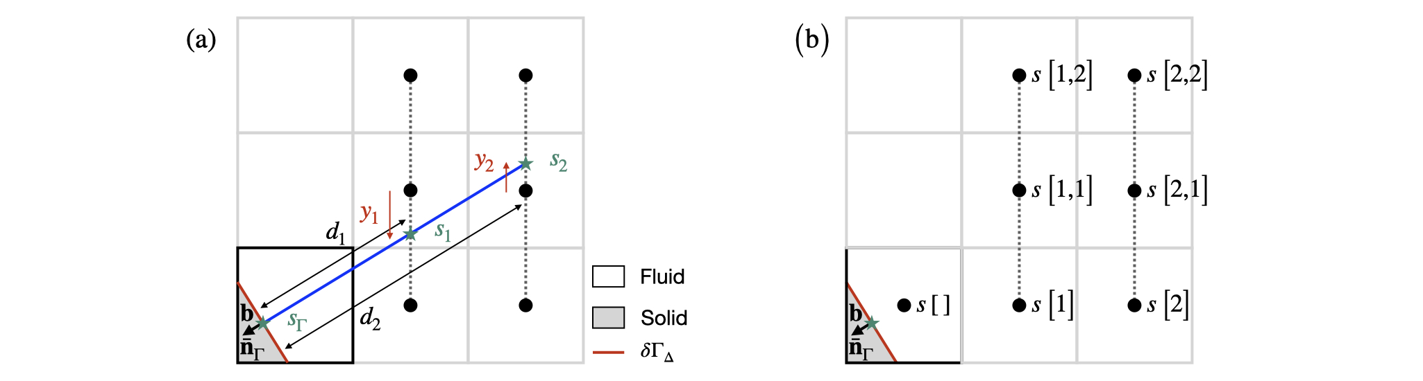
First, the function embed_evaluate() returns, if possible, the two interpolants s_1 and s_2 using a third-order quadratic (biquadratic in 3D) interpolation along the direction orthogonal to the principal direction of the normal vector -\mathbf{\bar{n}}_{\Gamma} as well as the positive distance d_1 and d_2 from the centroid \mathbf{b}. Without loss of generality, the 2D configuration presented in the previous Figure is considered, where the principal direction of the normal vector -\mathbf{\bar{n}}_{\Gamma} is the positive x-direction and d_1 = \frac{1 - b_x}{-\bar{n}_{\Gamma,x}} and d_2 = \frac{2 - b_x}{-\bar{n}_{\Gamma,x}}. The quantities s_1 and s_2 are then computed using cell-centered values of s taken from the 3 \times 2 (3 \times 3 \times 2 in 3D) stencil represented in the previous Figure, itself part of the 5 \times 5 (5\times 5\times 5 in 3D) stencil of the cut cell:
\begin{aligned} & s_1 = \left(s\left[1\right]\left(y_1 - 1\right) + s\left[1,2\right]\left(y_1 + 1.\right)\right)\frac{y_1}{2} - s\left[1,1\right]\left(y_1 - 1\right)\left(y_1 + 1\right) \\ & s_2 = \left(s\left[2\right]\left(y_2 - 1\right) + s\left[2,2\right]\left(y_2 + 1.\right)\right)\frac{y_2}{2} - s\left[2,1\right]\left(y_2 - 1\right)\left(y_2 + 1\right), \end{aligned} where y_1 = b_y + d_1\left[-\bar{n}_{\Gamma,y}\right] - 1 and y_2 = b_y + d_2\left[-\bar{n}_{\Gamma,y}\right] -1. Note here that the centroid \mathbf{b} and the distances d_1, d_2, y_1 and y_2 are defined in a coordinate system with origin the center of the cell and in which the cell size is unity and that the values of s are interpreted as point-value estimates at the center of full cells.
#define quadratic(x,a1,a2,a3)						\
  (((a1)*((x) - 1.) + (a3)*((x) + 1.))*(x)/2. - (a2)*((x) - 1.)*((x) + 1.))

foreach_dimension()
static inline void embed_evaluate_x (Point point, scalar s, scalar cs,
				     coord n, coord b,
				     double * d0, double * v0,
				     double * d1, double * v1)
{
  assert ((cs[]) > 0. && (cs[]) < 1.);
We use the normal pointing from solid to fluid.
  foreach_dimension()
    n.x = -n.x;
We compute the distance from the cell center d and the interpolated values v.
double d[2], v[2] = {nodata,nodata};We then assess if neighboring cells in the fluid domain are accessible (fs > 0).
  bool defined = true;
  foreach_dimension()
    if (defined && !fs.x[(n.x > 0.)])
      defined = false;
If neighbors are available, we perform a quadric (2D) or biquadratic (3D) interpolations. If not all neighbors all available, we do not compute a value to avoid using values of cells of the grid that are not topologically connected, which could prevent convergence of the multigrid solver.
  if (defined)
    for (int l = 0; l <= 1; l++) {
      //distance from p
      int i = (l + 1)*sign(n.x);
      d[l] = (i - b.x)/(n.x);
      // projecion in the y-direction
      double y1 = (b.y) + (d[l])*(n.y);
      int j = y1 > 0.5 ? 1 : y1 < -0.5 ? -1 : 0;
      y1 -= j;
#if dimension == 2
      // quadratic interpolation
      if (fs.x[i + (i < 0),j] && fs.y[i,j] && fs.y[i,j+1] &&
	  cs[i,j-1] && cs[i,j] && cs[i,j+1] &&
	  (emerged || (csm1[i,j-1] && csm1[i,j] && csm1[i,j+1])))
	v[l] = quadratic (y1, (s[i,j-1]), (s[i,j]), (s[i,j+1]));
#else // dimension == 3
      // projecion in the z-direction
      double z1 = (b.z) + (d[l])*(n.z);
      int k = z1 > 0.5 ? 1 : z1 < -0.5 ? -1 : 0;
      z1 -= k;
      bool defined = fs.x[i + (i < 0),j,k];
      for (int m = -1; m <= 1 && defined; m++)
	if (!fs.y[i,j,k+m] || !fs.y[i,j+1,k+m] ||
	    !fs.z[i,j+m,k] || !fs.z[i,j+m,k+1] ||
	    !cs[i,j+m,k-1] || !cs[i,j+m,k] || !cs[i,j+m,k+1] ||
	    (!emerged && (!csm1[i,j+m,k-1] || !csm1[i,j+m,k] || !csm1[i,j+m,k+1])))
	  defined = false;
      if (defined)
	// bi-quadratic interpolation
	v[l] =
	  quadratic (z1,
		     quadratic (y1,
				(s[i,j-1,k-1]), (s[i,j,k-1]), (s[i,j+1,k-1])),
		     quadratic (y1,
				(s[i,j-1,k]),   (s[i,j,k]),   (s[i,j+1,k])),
		     quadratic (y1,
				(s[i,j-1,k+1]), (s[i,j,k+1]), (s[i,j+1,k+1])));
#endif // dimension == 3
      else
	break;
    }
  *d0 = d[0]; *v0 = v[0];
  *d1 = d[1]; *v1 = v[1];
}

void embed_evaluate (Point point, scalar s, scalar cs,
		     coord n, coord b,
		     double * d0, double * v0,
		     double * d1, double * v1)
{
#if dimension == 2
  if (fabs(n.x) >= fabs(n.y))
    embed_evaluate_x (point, s, cs, n, b, d0, v0, d1, v1);
  else
    embed_evaluate_y (point, s, cs, n, b, d0, v0, d1, v1);
#else // dimension == 3
  if (fabs(n.x) >= fabs(n.y)) {
    if (fabs(n.x) >= fabs(n.z))
      embed_evaluate_x (point, s, cs, n, b, d0, v0, d1, v1);
    else
      embed_evaluate_z (point, s, cs, n, b, d0, v0, d1, v1);
  }
  else if (fabs(n.y) >= fabs(n.z))
    embed_evaluate_y (point, s, cs, n, b, d0, v0, d1, v1);
  else
    embed_evaluate_z (point, s, cs, n, b, d0, v0, d1, v1);
#endif // dimension == 3
}
Then, the function dirichlet_gradient returns the following second-order discretization of the gradient in the direction of the unit normal vector -\mathbf{\bar{n}}_{\Gamma} (normalised using the Euclidean norm, not the box norm): \nabla_\Gamma s = \frac{1}{d_2 - d_1}\left(\left(s_{\Gamma} - s_1\right)\frac{d_2}{d_1} - \left(s_{\Gamma} - s_2\right)\frac{d_1}{d_2}\right), where s_{\Gamma} is the Dirichlet boundary condition imposed at the centroid \mathbf{b} of the discrete rigid boundary \delta \Gamma_{\Delta} in the cut-cell.
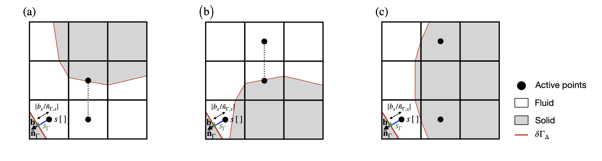
To maintain a robust computation of the embedded face gradient \nabla_{\Gamma} s in complex geometrical configurations, the previous equation is used only if the cells required to compute the first and second interpolants s_1 and s_2 are topologically connected. This means that a line unbroken by a solid cell or face connects the center of the current cut-cell \left[0,0\right] to the center of all cells in the stencils of both s_1 and s_2 (see function embed_evaluate_x()). If this is not the case, the situation is degenerate. Note that these degenerate cases were not considered in Johansen and Colella, 1998. The function dirichlet_gradient also returns the value the embedded face gradient \nabla_{\Gamma} s in the following two degenerate cases:
- if the stencil for s_2 is not topologically connected to the current cut-cell \left[0,0\right], the following first-order discretization of \nabla_{\Gamma} s is used: \nabla_\Gamma s = \frac{s_{\Gamma} - s_1}{d_1}.
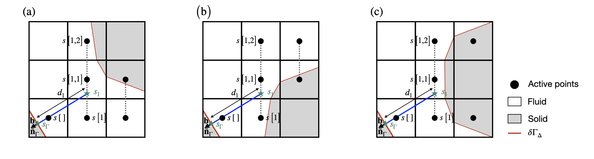
- if the stencil for s_1 is not topologically connected to the current cut-cell \left[0,0\right], a pathological situation is faced. In this case, the cell-centered value s\left[\,\right] is used to compute \nabla_\Gamma s: \nabla_\Gamma s = \frac{s_{\Gamma} - s[\,]}{\lvert b_x/\bar{n}_{\Gamma,x}\rvert}.
In practice, the function dirichlet_gradient also returns a
value stored in coef. The quantity coef*s[] must
be added to the value returned to obtain the gradient. Note however that
coef is non-zero only in the second degenerate case.
double dirichlet_gradient (Point point, scalar s, scalar cs,
			   coord n, coord b, double bc, double * coef)
{
  double d[2], v[2] = {nodata,nodata};
  embed_evaluate (point, s, cs, n, b, &d[0], &v[0], &d[1], &v[1]);
This is a degenerate case, we use the boundary value and the cell-center value to define the gradient.
  if (v[0] == nodata) {
#if dimension == 2
    if (fabs(n.x) >= fabs(n.y))
      d[0] = max(1e-3, fabs(b.x/n.x));
    else
      d[0] = max(1e-3, fabs(b.y/n.y));
#else // dimension == 3
    if (fabs(n.x) >= fabs(n.y)) {
      if (fabs(n.x) >= fabs(n.z))
	d[0] = max(1e-3, fabs(b.x/n.x));
      else
	d[0] = max(1e-3, fabs(b.z/n.z));
    }
    else if (fabs(n.y) >= fabs(n.z))
      d[0] = max(1e-3, fabs(b.y/n.y));
    else
      d[0] = max(1e-3, fabs(b.z/n.z));
#endif

    *coef = - 1./(d[0]*Delta);
    return bc/(d[0]*Delta);
  }
For non-degenerate cases, the gradient is obtained using either second- or third-order estimates.
  *coef = 0.;
  if (v[1] != nodata) // third-order gradient
    return (d[1]*(bc - v[0])/d[0] - d[0]*(bc - v[1])/d[1])/((d[1] - d[0])*Delta);
  return (bc - v[0])/(d[0]*Delta); // second-order gradient
}
Neumann boundary condition
Here, a Neumann boundary condition \nabla_{\Gamma} s is imposed at the centroid \mathbf{b}. In this case, the function neumann_scalar() returns the value of the scalar s in the cut-cell based on the discretization of the embedde face gradient {\nabla}_{\Gamma} s detailled in the function dirichlet_gradient(). Similar degenerate cases are considered.
double neumann_scalar (Point point, scalar s, scalar cs,
		       coord n, coord b, double grad, double * coef)
{
  double d[2], v[2] = {nodata,nodata};
  embed_evaluate (point, s, cs, n, b, &d[0], &v[0], &d[1], &v[1]);
This is a degenerate case, we use the gradient boundary condition and the cell-center value to define the value of the scalar at the boundary.
  if (v[0] == nodata) {

#if dimension == 2
    if (fabs(n.x) >= fabs(n.y))
      d[0] = max(1e-3, fabs(b.x/n.x));
    else
      d[0] = max(1e-3, fabs(b.y/n.y));
#else // dimension == 3
    if (fabs(n.x) >= fabs(n.y)) {
      if (fabs(n.x) >= fabs(n.z))
	d[0] = max(1e-3, fabs(b.x/n.x));
      else
	d[0] = max(1e-3, fabs(b.z/n.z));
    }
    else if (fabs(n.y) >= fabs(n.z))
      d[0] = max(1e-3, fabs(b.y/n.y));
    else
      d[0] = max(1e-3, fabs(b.z/n.z));
#endif

    *coef = 1.;
    return (grad)*(d[0]*Delta);
  }
For non-degenerate cases, the value of the scalar at the boundary is obtained using either second- or third-order estimates.
  *coef = 0.;
  if (v[1] != nodata) // third-order value
    return ((grad)*((d[1] - d[0])*Delta) + v[0]*d[1]/d[0] - v[1]*d[0]/d[1])/(d[1]/d[0] - d[0]/d[1]);
  return (grad)*(d[0]*Delta) + v[0]; // second-order value
}
Viscous flux through the discrete rigid boundary in a cut-cell
The function embed_flux() computes the viscous flux through the discrete rigid boundary \delta \Gamma_{\Delta} in a cut-cell, in the case where the viscosity is constant (times the metric): \int_{\delta \Gamma_{\Delta}} \mu \nabla_{\Gamma} s\, \mathrm{d}S, with \mathrm{d}S the elementary boundary surface and \nabla_{\Gamma}s is the embedded face gradient described previously.
In practice, as this function is intented to be used with the multigrid Poisson solver which is based on the volume integration of the residual b - \mathbf{\nabla} \cdot \left(\mu \mathbf{\nabla} s\right), the value: -\frac{1}{\Delta^{D}}\left(\frac{\bar{\mu}\left[\,\right]}{\bar{f}\left[\,\right]} f_{\Gamma} \Delta^{D-1} \nabla_{\Gamma} s\right) = -\frac{1}{\Delta}\left(\frac{\bar{\mu}\left[\,\right]}{\bar{f}\left[\,\right]}f_{\Gamma} \nabla_{\Gamma} s\right),
is returned in val. The function also returns 0 in non-degenerate cases. In degenerate cases, it returns a non-zero value which corresponds to the quantity: -\frac{1}{\Delta}\left(\frac{\bar{\mu}\left[\,\right]}{\bar{f}\left[\,\right]}f_{\Gamma} \,\mathrm{coef}\right), where coef is the quantity defined by the function dirichlet_gradient(). The user must then multiply this quantity by s[] and add it to the flux.
double embed_flux (Point point, scalar s, face vector mu, double * val)
{
If the cell does not contain a fragment of embedded boundary, the flux is zero.
  *val = 0.;
  if (cs[] >= 1. || cs[] <= 0.)
    return 0.;
If the boundary condition is homogeneous Neumann, the flux is zero.
  bool dirichlet;
  double grad = s.boundary[embed] (point, point, s, &dirichlet);
  if (!grad && !dirichlet)
    return 0.;
Otherwise, we compute the normal, area and barycenter of the discrete rigid boundary \delta \Gamma_{\Delta} in the cut-cell.
  coord n, b;
  double area = embed_geometry (point, &b, &n);
If the boundary condition is Dirichlet, we need to compute the normal gradient.
  double coef = 0.;
  if (dirichlet)
    grad = dirichlet_gradient (point, s, cs, n, b, grad, &coef);
We retrieve the (average) value of \mu without the metric.
  double mua = 0., fa = 0.;
  foreach_dimension() {
    mua += mu.x[] + mu.x[1];
    fa  += fs.x[] + fs.x[1];
  }
  *val = - mua/(fa + SEPS)*grad*area/Delta;
  return - mua/(fa + SEPS)*coef*area/Delta;
}
If the viscosity is not constant, the previous function embed_flux() cannot be used to compute the viscous flux. The function embed_stress_flux() therefore computes the flux through the discrete rigid boundary \delta \Gamma_{\Delta} in a cut-cell, in the case where the viscosity is not constant (times the metric): \mathbf{F}_{\mu} = \int_{\delta \Gamma_{\Delta}} \mu (\mathbf{\nabla} \mathbf{u} + \mathbf{\nabla}^T \mathbf{u}) \cdot\mathbf{n}_{\Gamma}\, \mathrm{d}S with \mathrm{d}S the elementary boundary surface.
We follow here the steps described when computing the viscous force F_\mu. The flux is returned in Fmu and the flux correction for degenerate cases in returned in Fval, which must be multiplied by s\left[\,\right] and added to Fmu.
void embed_stress_flux (Point point, vector s, face vector mu,
			coord * Fmu, coord * Fval)
{
If the cell does not contain a fragment of embedded boundary, the flux is zero.
  if (cs[] >= 1. || cs[] <= 0.) {
    foreach_dimension()
      Fmu->x = 0., Fval->x = 0.;
    return;
  }
If the viscosity is not zero, we first need to retrieve the local value of the viscosity (ideally at the barycentre of the embedded fragment). This is not completely trivial since it is defined on the faces of the cell. We use a surface-fraction-weighted average value.
  double mua = 0., fa = 0.;
  foreach_dimension() {
    mua += mu.x[] + mu.x[1];
    fa  += fs.x[] + fs.x[1];
  }
  mua /= (fa + SEPS);
We then compute the normal, area and barycenter of the discrete rigid boundary \delta \Gamma_{\Delta} in the cut-cell.
  coord n, b;
  double area = embed_geometry (point, &b, &n);
Here, we do not use the embed_gradient function directly as we need to account separately (using Fval) for the additional term return in val by the function dirichlet_gradient in degenerate cases.
  coord dsdn = {0., 0., 0.}, val = {0., 0., 0.};
  foreach_dimension() {
    bool dirichlet;
    double vb = s.x.boundary[embed] (point, point, s.x, &dirichlet);
    if (dirichlet)
      dsdn.x = dirichlet_gradient (point, s.x, cs, n, b, vb, &(val.x));
    else
      dsdn.x = vb;
    if (dsdn.x == nodata)
      dsdn.x = 0., val.x = 0.;
  }
We finally update the the flux, following the sign and scaling conventions of embed_flux.
#if dimension == 2
      foreach_dimension() {
        Fmu->x  = -area*mua*(dsdn.x*(sq (n.x) + 1.) +
			     (dsdn.y + val.y*s.y[])*n.x*n.y)/Delta;
        Fval->x = -area*mua*(val.x*(sq (n.x) + 1.))/Delta;
      }
#else // dimension == 3
      foreach_dimension() {
        Fmu->x  = -area*mua*(dsdn.x*(sq (n.x) + 1.) +
			     (dsdn.y + val.y*s.y[])*n.x*n.y +
			     (dsdn.z + val.z*s.z[])*n.x*n.z)/Delta;
        Fval->x = -area*mua*(val.x*(sq (n.x) + 1.))/Delta;
      }
#endif // dimension
/*   // As an example, for a constant viscosity (i.e. D = mu grad u), we would have:   */
/* #if dimension == 2 */
/*       foreach_dimension() { */
/*         Fmu->x  = -area*mua*(dsdn.x*(1.))/Delta; */
/*         Fval->x = -area*mua*(val.x*(1.))/Delta; */
/*       } */
/* #else // dimension == 3 */
/*       foreach_dimension() { */
/*         Fmu->x  = -area*mua*(dsdn.x*(1.))/Delta; */
/*         Fval->x = -area*mua*(val.x*(1.))/Delta; */
/*       } */
/* #endif // dimension */
  return;
}
Extrapolation of a cell-centered scalar - Emerged cells
The function embed_extrapolate() returns the value of a scalar s linearly extrapolated (second-order) at the position c in a cut-cell, expressed in a coordinate system with origin the cell center and in which the cell size is unity, in the direction of the normal vector \mathbf{\bar{n}}_{\Gamma} to the discrete rigid boundary \delta \Gamma_{\Delta}: s = \frac{s_1\,d_2 - s_2\,d_1}{d_2 - d_1}, where the interpolants s_1, s_2 and the distances d_1 and d_2 are computed by the function embed_evaluate(). If the stencils for s_1 or s_2 are not topologically connected to the cut-cell \left[0,0\right], we use a similar approach as in the function dirichlet_gradient() to treat degenerate cases. We use here a simple injection using either a neighboring value or the user provided value sb (typically the boundary condition).

#define linear_lagrange(x,x1,a1,x2,a2)			\
  (a1*(x - x2)/(x1 - x2) + a2*(x - x1)/(x2 - x1))

double embed_extrapolate (Point point, scalar s, scalar cs,
			  coord n, coord c, double sb)
{
  double d[2], v[2] = {nodata,nodata};
  embed_evaluate (point, s, cs, n, c, &d[0], &v[0], &d[1], &v[1]);
This is a degenerate case, we use the “boundary” value sb.
  if (v[0] == nodata)
    return (sb);
For non-degenerate cases, the extrapolated value is obtained using first- or second-order (linear) estimates.
  if (v[1] != nodata) // second-order linear extrapolation
    return (linear_lagrange (0.,d[0],v[0],d[1],v[1]));
  else // first-order injection
    return v[0];
}
This next function can also be used to extrapolate the value of the sca;ar s at the position c in the cell, expressed in a coordinate system with origin the cell center and in which the cell size is unity. However, contrary to the function embed_extrapolate(), it uses a least square method to fit a quadratic polynomial in the 5x5 stencil of the cell and does not required any information about the embedded boundary. If linear = true, then a linear polynomial and the 3x3 stencil of the cell are used. Details of the methodology are provide in myquadratic.h.
#include "myquadratic.h"

double embed_extrapolate_ls (Point point, scalar s, scalar cs,
			     coord c, bool linear)
{
We first initialize the linear system.
  int nc = 0; // Number of cells used to fill the linear system
  QuadraticFit fit;
  quadratic_fit_init (&fit, c, linear);
We fill the linear system using values from the stencil of the current cell. However, we make sure to use only cells that are topologically connected to the current cell (to be improved?).
If we use only a linear extrapolation, we use the 3x3 stencil around the current cell.
  int neigh = 2;
  if (linear)
    neigh = 1;

  for (int i = -neigh; i <= neigh; i++) {
    for (int j = -neigh; j <= neigh; j++) {
#if dimension == 2
      if ((i || j) &&
	  cs[i,j] &&
	  cs[i - (i > 0) + (i < 0), j] &&
	  cs[i, j - (j > 0) + (j < 0)] &&
	  (
	   i && !j ? fs.x[i + (i < 0), j] :
	   !i && j ? fs.y[i, j + (j < 0)] :
	   (fs.x[i + (i < 0), j] && fs.y[i, j + (j < 0)])
	   ) &&
	  (emerged || csm1[i,j])) {
	nc ++;
	coord o = {i,j};
	quadratic_fit_add (&fit, o, s[i,j]);
      }
#else // dimension == 3
      for (int k = -neigh; k <= neigh; k++) {
	if ((i || j || k) &&
	    cs[i,j,k] &&
	    cs[i - (i > 0) + (i < 0), j, k] &&
	    cs[i, j - (j > 0) + (j < 0), k] &&
	    cs[i, j, k - (k > 0) + (k < 0)] &&
	    (
	     i  && !j && !k ? fs.x[i + (i < 0), j, k] :
	     !i && j  && !k ? fs.y[i, j + (j < 0), k] :
	     !i && !j && k  ? fs.z[i, j, k + (k < 0)] :
	     i  && j  && !k ? (fs.x[i + (i < 0), j, k] && fs.y[i, j + (j < 0), k]) :
	     i  && !j && k  ? (fs.x[i + (i < 0), j, k] && fs.z[i, j, k + (k < 0)]) :
	     !i && j  && k  ? (fs.y[i, j + (j < 0), k] && fs.z[i, j, k + (k < 0)]) :
	     (fs.x[i + (i < 0), j, k] && fs.y[i, j + (j < 0), k] && fs.z[i, j, k + (k < 0)])
	     ) &&
	    (emerged || csm1[i,j,k])) {
	  nc ++;
	  coord o = {i, j, k};
	  quadratic_fit_add (&fit, o, s[i,j,k]);
	}
      }
#endif // dimension
    }
  }
We finally solve the linear system using a least-square method. We output the constant coefficient that corresponds to the interpolated/extrapolated value in x=c.
  quadratic_fit_solve (&fit, nc);
  return fit.a[0];
}
Surface force and torque and vorticity
We first define a function which computes \mathbf{\nabla}\mathbf{u}\cdot\mathbf{n}_{\Gamma} while taking into account the Dirichlet or Neumann boundary conditions on the discrete rigid boundary \delta \Gamma_{\Delta} in a cut-cell.
static inline
coord embed_gradient (Point point, vector u, coord b, coord n)
{
  coord dudn;
  foreach_dimension() {
    bool dirichlet;
    double vb = u.x.boundary[embed] (point, point, u.x, &dirichlet);
    if (dirichlet) {
      double val;
      dudn.x = dirichlet_gradient (point, u.x, cs, n, b, vb, &val);
      dudn.x += u.x[]*val; // For pathological situations
    }
    else // Neumann
      dudn.x = vb;
    if (dudn.x == nodata)
      dudn.x = 0.;
  }
  return dudn;
}
Surface force
The force exerted by the fluid on the solid can be written: \mathbf{F}_{\Gamma} = - \int_{\partial \Gamma} ( - p\mathbf{I} + 2 \mu \mathbf{D}) \cdot \mathbf{n}_{\Gamma} \, \mathrm{d} S, with \delta \Gamma the rigid boundary. It can be further decomposed into a pressure (i.e. “form”) drag: \mathbf{F}_p = \int_{\partial \Gamma} p \, \mathbf{n}_{\Gamma} \, \mathrm{d} S, and a viscous drag: \mathbf{F}_{\mu} = - \int_{\partial \Gamma} 2 \mu \mathbf{D} \cdot \mathbf{n}_{\Gamma} \, \mathrm{d} S. These two vectors are computed by the embed_force() function.
trace
void embed_force (scalar p, vector u, face vector mu, coord * Fp, coord * Fmu)
{
  coord Fps = {0}, Fmus = {0};
  foreach (reduction(+:Fps) reduction(+:Fmus), nowarning)
    if (cs[] > 0. && cs[] < 1.) {
To compute the pressure force, we first get the coordinates of the barycentre of the discrete rigid boundary \delta \Gamma_{\Delta} in the cut-cell, its area and normal, and then interpolate the pressure field on the surface.
      coord n, b;
      double area = embed_geometry (point, &b, &n);
      area *= pow (Delta, dimension - 1);

      double Fn = area*embed_interpolate (point, p, b);
      foreach_dimension()
	Fps.x += Fn*n.x;
To compute the viscous force, we first need to retrieve the local value of the viscosity (ideally at the barycentre of the discrete rigid boundary \delta \Gamma_{\Delta}). This is not completely trivial since it is defined on the faces of the cell. We use a surface-fraction-weighted average value.
      if (constant(mu.x) != 0.) {
	double mua = 0., fa = 0.;
	foreach_dimension() {
	  mua += mu.x[] + mu.x[1];
	  fa  += fs.x[] + fs.x[1];
	}
	mua /= (fa + SEPS);
To compute the viscous force, we need to take into account the (Dirichlet or Neumann) boundary conditions for the velocity on the surface. We only know how to do this when computing the normal gradient \mathbf{\nabla}\mathbf{u}\cdot\mathbf{n} using the embed_gradient() function. We thus need to re-express the viscous force using only normal derivatives of the velocity field.
If we assume that \mathbf{u} is constant on the discrete rigid boundary \delta \Gamma_{\Delta} in the cut-cell, then: \mathbf{{\nabla}} \mathbf{u} \cdot \mathbf{t}= \mathbf{0}, with \mathbf{t} the unit tangent vector to the boundary. We thus have the relations: \mathbf{{\nabla}} \mathbf{u} = \left( \mathbf{{\nabla}} \mathbf{u} \cdot \mathbf{n} \right) \mathbf{n} + \left( \mathbf{{\nabla}} \mathbf{u} \cdot \mathbf{t} \right) \mathbf{t} = \left( \mathbf{{\nabla}} \mathbf{u} \cdot \mathbf{n} \right) \mathbf{n} \mathbf{D}= \frac{1}{2} \left( \mathbf{{\nabla}} \mathbf{u} + \mathbf{{\nabla}}^T \mathbf{u} \right) = \frac{1}{2} \left(\begin{array}{cc} 2 \left( \mathbf{{\nabla}} u \cdot \mathbf{n} \right) n_x & \left( \mathbf{{\nabla}} u \cdot \mathbf{n} \right) n_y + \left( \mathbf{{\nabla}} v \cdot \mathbf{n} \right) n_x & \left( \mathbf{{\nabla}} u \cdot \mathbf{n} \right) n_z + \left( \mathbf{{\nabla}} w \cdot \mathbf{n} \right) n_x\\ \left( \mathbf{{\nabla}} u \cdot \mathbf{n} \right) n_y + \left( \mathbf{{\nabla}} v \cdot \mathbf{n} \right) n_x & 2 \left( \mathbf{{\nabla}} v \cdot \mathbf{n} \right) n_y & \left( \mathbf{{\nabla}} v \cdot \mathbf{n} \right) n_z + \left( \mathbf{{\nabla}} w \cdot \mathbf{n} \right) n_y\\ \left( \mathbf{{\nabla}} u \cdot \mathbf{n} \right) n_z + \left( \mathbf{{\nabla}} w \cdot \mathbf{n} \right) n_x & \left( \mathbf{{\nabla}} v \cdot \mathbf{n} \right) n_z + \left( \mathbf{{\nabla}} w \cdot \mathbf{n} \right) n_y & 2 \left( \mathbf{{\nabla}} w \cdot \mathbf{n} \right) n_z\\ \end{array}\right), which allows us to write the viscous force as: \mathbf{F}_{\mu} = - \int_{\delta\Gamma} \left(\begin{array}{c} \left[2 \mu \left( \mathbf{{\nabla}} u \cdot \mathbf{n} \right) n_x \right] n_x + \mu \left[ \left( \mathbf{{\nabla}} u \cdot \mathbf{n} \right) n_y + \left( \mathbf{{\nabla}} v \cdot \mathbf{n} \right) n_x \right] n_y + \mu \left[ \left( \mathbf{{\nabla}} u \cdot \mathbf{n} \right) n_z + \left( \mathbf{{\nabla}} w \cdot \mathbf{n} \right) n_x \right] n_z\\ \left[2 \mu \left( \mathbf{{\nabla}} v \cdot \mathbf{n} \right) n_y \right] n_y + \mu \left[ \left( \mathbf{{\nabla}} u \cdot \mathbf{n} \right) n_y + \left( \mathbf{{\nabla}} v \cdot \mathbf{n} \right) n_x \right] n_x + \mu \left[ \left( \mathbf{{\nabla}} v \cdot \mathbf{n} \right) n_z + \left( \mathbf{{\nabla}} w \cdot \mathbf{n} \right) n_y \right] n_z\\ \left[2 \mu \left( \mathbf{{\nabla}} w \cdot \mathbf{n} \right) n_z \right] n_z + \mu \left[ \left( \mathbf{{\nabla}} u \cdot \mathbf{n} \right) n_z + \left( \mathbf{{\nabla}} w \cdot \mathbf{n} \right) n_x \right] n_x + \mu \left[ \left( \mathbf{{\nabla}} v \cdot \mathbf{n} \right) n_z + \left( \mathbf{{\nabla}} w \cdot \mathbf{n} \right) n_y \right] n_y\\ \end{array}\right) \mathbf{F}_{\mu} = - \int_{\delta\Gamma} \left(\begin{array}{c} \mu \left[ \left( \mathbf{{\nabla}} u \cdot \mathbf{n} \right) (n^2_x + 1) + \left( \mathbf{{\nabla}} v \cdot \mathbf{n} \right) n_x n_y + \left( \mathbf{{\nabla}} w \cdot \mathbf{n} \right) n_x n_z \right]\\ \mu \left[ \left( \mathbf{{\nabla}} v \cdot \mathbf{n} \right) (n^2_y + 1) + \left( \mathbf{{\nabla}} u \cdot \mathbf{n} \right) n_x n_y + \left( \mathbf{{\nabla}} w \cdot \mathbf{n} \right) n_y n_z \right]\\ \mu \left[ \left( \mathbf{{\nabla}} w \cdot \mathbf{n} \right) (n^2_z + 1) + \left( \mathbf{{\nabla}} u \cdot \mathbf{n} \right) n_x n_z + \left( \mathbf{{\nabla}} v \cdot \mathbf{n} \right) n_y n_z \right] \end{array}\right)
	coord dudn = embed_gradient (point, u, b, n);
#if dimension == 2
	foreach_dimension()
	  Fmus.x -= area*mua*(dudn.x*(sq (n.x) + 1.) +
			      dudn.y*n.x*n.y);
#else // dimension == 3
	foreach_dimension()
	  Fmus.x -= area*mua*(dudn.x*(sq (n.x) + 1.) +
			      dudn.y*n.x*n.y +
			      dudn.z*n.x*n.z);
#endif // dimension
      }
    }

  *Fp = Fps; *Fmu = Fmus;
}
The function embed_color_force computes the force on the colored embedded boundaries, using the user defined color scalar color.
void embed_color_force (scalar p, vector u, face vector mu, scalar color, coord * Fp, coord * Fmu)
{
  coord Fps = {0}, Fmus = {0};
  foreach (reduction(+:Fps) reduction(+:Fmus))
    if (cs[] > 0. && cs[] < 1. && color[] > 0. && color[] < 1.) {

      coord n, b;
      double area = embed_geometry (point, &b, &n);
      area *= pow (Delta, dimension - 1);

      double Fn = area*embed_interpolate (point, p, b);
      foreach_dimension()
	Fps.x += Fn*n.x;

      if (constant(mu.x) != 0.) {
	double mua = 0., fa = 0.;
	foreach_dimension() {
	  mua += mu.x[] + mu.x[1];
	  fa  += fs.x[] + fs.x[1];
	}
	mua /= (fa + SEPS);

	coord dudn = embed_gradient (point, u, b, n);
#if dimension == 2
	foreach_dimension()
	  Fmus.x -= area*mua*(dudn.x*(sq (n.x) + 1.) +
			      dudn.y*n.x*n.y);
#else // dimension == 3
	foreach_dimension()
	  Fmus.x -= area*mua*(dudn.x*(sq (n.x) + 1.) +
			      dudn.y*n.x*n.y +
			      dudn.z*n.x*n.z);
#endif // dimension
      }
    }

  *Fp = Fps; *Fmu = Fmus;
}
Surface torque
The torque exerted by the fluid on the solid can be written: \mathbf{T}_{\Gamma} = - \int_{\partial \Gamma} (\mathbf{x} - \mathbf{x}_{\Gamma})\times( - p\mathbf{I} + 2 \mu \mathbf{D}) \cdot \mathbf{n}_{\Gamma} \, \mathrm{d} S, with \delta \Gamma the rigid boundary and \mathbf{x}_{\Gamma} its barycenter. It can be further decomposed into a pressure (i.e. “form”) torque: \mathbf{T}_p = \int_{\partial \Gamma} (\mathbf{x} - \mathbf{x}_{\Gamma})\times (p \, \mathbf{n}_{\Gamma}) \, \mathrm{d} \Gamma, and a viscous torque: \mathbf{T}_{\mu} = - \int_{\partial \Gamma} (\mathbf{x} - \mathbf{x}_{\Gamma})\times (2 \mu \mathbf{D} \cdot \mathbf{n}_{\Gamma}) \, \mathrm{d} \Gamma. These two vectors are computed by the embed_torque() function, which ressembles the function embed_force().
trace
void embed_torque (scalar p, vector u, face vector mu, coord c, coord * Tp, coord * Tmu)
{
  coord Tps = {0}, Tmus = {0};
  foreach (reduction(+:Tps) reduction(+:Tmus))
    if (cs[] > 0. && cs[] < 1.) {

      coord n, b;
      double area = embed_geometry (point, &b, &n);
      area *= pow (Delta, dimension - 1);
In addition to the quantities computed in the function embed_force(), we also compute the relative coordinates \mathbf{x} - \mathbf{x}_{\Gamma}.
      // The coordinate x,y,z are not permuted with foreach_dimension()
      coord r = {x,y,z};
      // In case of a periodic domain, we shift the position of the center
      foreach_dimension() {
	r.x += b.x*Delta - c.x;
	if (Period.x) {
	  if (fabs (r.x) > fabs (r.x + (L0)))
	    r.x += (L0);
	  if (fabs (r.x) > fabs (r.x - (L0)))
	    r.x -= (L0);
	}
      }

      double Fn = area*embed_interpolate (point, p, b);
#if dimension == 2
      Tps.x += Fn*(r.x*n.y - r.y*n.x);
      Tps.y = Tps.x;
#else // dimension == 3
      foreach_dimension()
	Tps.x += Fn*(r.y*n.z - r.z*n.y);
#endif // dimension

      if (constant(mu.x) != 0.) {
	double mua = 0., fa = 0.;
	foreach_dimension() {
	  mua += mu.x[] + mu.x[1];
	  fa  += fs.x[] + fs.x[1];
	}
	mua /= (fa + SEPS);

	coord dudn = embed_gradient (point, u, b, n);
	coord Fmus = {0};
#if dimension == 2
	foreach_dimension()
	  Fmus.x = -area*mua*(dudn.x*(sq (n.x) + 1.) +
			      dudn.y*n.x*n.y);
#else // dimension == 3
	foreach_dimension()
	  Fmus.x = -area*mua*(dudn.x*(sq (n.x) + 1.) +
			      dudn.y*n.x*n.y +
			      dudn.z*n.x*n.z);
#endif // dimension

#if dimension == 2
	Tmus.x += r.x*Fmus.y - r.y*Fmus.x;
	Tmus.y = Tmus.x;
#else // dimension == 3
	foreach_dimension()
	  Tmus.x += r.y*Fmus.z - r.z*Fmus.y;
#endif // dimension
      }
    }

  *Tp = Tps; *Tmu = Tmus;
}
The function embed_color_torque computes the torque on the colored embedded boundaries, using the user defined color scalar color.
void embed_color_torque (scalar p, vector u, face vector mu, scalar color, coord c, coord * Tp, coord * Tmu)
{
  coord Tps = {0}, Tmus = {0};
  foreach (reduction(+:Tps) reduction(+:Tmus))
    if (cs[] > 0. && cs[] < 1. && color[] > 0. && color[] < 1.) {

      coord n, b;
      double area = embed_geometry (point, &b, &n);
      area *= pow (Delta, dimension - 1);
In addition to the quantities computed in the function embed_force(), we also compute the relative coordinates \mathbf{x} - \mathbf{x}_{\Gamma}.
      // The coordinate x,y,z are not permuted with foreach_dimension()
      coord r = {x,y,z};
      // In case of a periodic domain, we shift the position of the center
      foreach_dimension() {
	r.x += b.x*Delta - c.x;
	if (Period.x) {
	  if (fabs (r.x) > fabs (r.x + (L0)))
	    r.x += (L0);
	  if (fabs (r.x) > fabs (r.x - (L0)))
	    r.x -= (L0);
	}
      }

      double Fn = area*embed_interpolate (point, p, b);
#if dimension == 2
      Tps.x += Fn*(r.x*n.y - r.y*n.x);
      Tps.y = Tps.x;
#else // dimension == 3
      foreach_dimension()
	Tps.x += Fn*(r.y*n.z - r.z*n.y);
#endif // dimension

      if (constant(mu.x) != 0.) {
	double mua = 0., fa = 0.;
	foreach_dimension() {
	  mua += mu.x[] + mu.x[1];
	  fa  += fs.x[] + fs.x[1];
	}
	mua /= (fa + SEPS);

	coord dudn = embed_gradient (point, u, b, n);
	coord Fmus = {0};
#if dimension == 2
	foreach_dimension()
	  Fmus.x = -area*mua*(dudn.x*(sq (n.x) + 1.) +
			      dudn.y*n.x*n.y);
#else // dimension == 3
	foreach_dimension()
	  Fmus.x = -area*mua*(dudn.x*(sq (n.x) + 1.) +
			      dudn.y*n.x*n.y +
			      dudn.z*n.x*n.z);
#endif // dimension

#if dimension == 2
	Tmus.x += r.x*Fmus.y - r.y*Fmus.x;
	Tmus.y = Tmus.x;
#else // dimension == 3
	foreach_dimension()
	  Tmus.x += r.y*Fmus.z - r.z*Fmus.y;
#endif // dimension
      }
    }

  *Tp = Tps; *Tmu = Tmus;
}
Surface vorticity
In two dimensions, the function embed_vorticity() returns the vorticity of velocity field \mathbf{u} on the surface of the discrete rigid boundary \delta \Gamma_{\Delta} contained in a cut-cell, with \mathbf{b} the barycenter of and \mathbf{n}_{\Gamma} the inwards unit normal vector to the discrete rigid boundary.
#if dimension == 2
double embed_vorticity (Point point, vector u, coord b, coord n)
{
We compute \mathbf{{\nabla}}\mathbf{u}\cdot\mathbf{n}_{\Gamma}, taking the boundary conditions into account.
coord dudn = embed_gradient (point, u, b, n);The vorticity is then obtained using the relations \omega = \partial_x v - \partial_y u = \left( \mathbf{{\nabla}} v \cdot \mathbf{n}_{\Gamma} \right) n_x - \left( \mathbf{{\nabla}} u \cdot \mathbf{n}_{\Gamma} \right) n_y
  return dudn.y*n.x - dudn.x*n.y;
}
#endif // dimension == 2
Prolongation for the multigrid solver
We use a simplified prolongation operator for the multigrid solver i.e. simple injection if bilinear interpolation would use values which are fully contained within the embedded boundary.
#if MULTIGRID
static inline double bilinear_embed (Point point, scalar s)
{
  if (!coarse(cs)) {
    /* assert (coarse(s) == 0.); */
    /* return coarse(s); // 0 */
    return 0;
  }
  if (!coarse(cs,child.x) ||
      (!emerged && !coarse(csm1,child.x)))
    return coarse(s);
#if dimension >= 2
  if (!coarse(cs,0,child.y) || !coarse(cs,child.x,child.y) ||
      (!emerged && (!coarse(csm1,0,child.y) || !coarse(csm1,child.x,child.y))))
    return coarse(s);
#endif
#if dimension >= 3
  if (!coarse(cs,0,0,child.z) || !coarse(cs,child.x,0,child.z) ||
      !coarse(cs,0,child.y,child.z) || !coarse(cs,child.x,child.y,child.z) ||
      (!emerged &&
       (!coarse(csm1,0,0,child.z) || !coarse(csm1,child.x,0,child.z) ||
	!coarse(csm1,0,child.y,child.z) || !coarse(csm1,child.x,child.y,child.z))))
    return coarse(s);
#endif
  return bilinear (point, s);
}
Another option would be to use interpolation functions similar to the ones used on trees.
static inline double bilinear_embed_2 (Point point, scalar s)
{
  if (!coarse(cs)) {
    assert (coarse(s) == 0.);
    return coarse(s); // 0
  }
  else {
    assert (coarse(cs));
    int i = (child.x + 1)/2, j = (child.y + 1)/2;
#if dimension == 2
    if (coarse(fs.x,i) > 0.25 && coarse(fs.y,0,j) > 0.25 &&
	(coarse(cs) == 1. || coarse(cs,child.x) == 1. ||
	 coarse(cs,0,child.y) == 1. || coarse(cs,child.x,child.y) == 1.) &&
	(emerged || (coarse(csm1) && coarse(csm1,child.x) &&
		     coarse(csm1,0,child.y) && coarse(csm1,child.x,child.y)))) {
      assert (coarse(cs,child.x) && coarse(cs,0,child.y));
      if (coarse(fs.x,i,child.y) && coarse(fs.y,child.x,j)) {
	// bilinear interpolation
	assert (coarse(cs,child.x,child.y));
	return (9.*coarse(s) +
		3.*(coarse(s,child.x) + coarse(s,0,child.y)) +
		coarse(s,child.x,child.y))/16.;
      }
      else
	// triangular interpolation
	return (2.*coarse(s) + coarse(s,child.x) + coarse(s,0,child.y))/4.;
    }
    else if (coarse(cs,child.x,child.y) &&
	     ((coarse(fs.x,i) && coarse(fs.y,child.x,j)) ||
	      (coarse(fs.y,0,j) && coarse(fs.x,i,child.y))) &&
	     (emerged || (coarse(csm1) && coarse(csm1,child.x,child.y)))) {
      // diagonal interpolation
      return (3.*coarse(s) + coarse(s,child.x,child.y))/4.;
    }
#else // dimension == 3
    int k = (child.z + 1)/2;
    if (coarse(fs.x,i) > 0.25 && coarse(fs.y,0,j) > 0.25 &&
	coarse(fs.z,0,0,k) > 0.25 &&
	(coarse(cs) == 1. || coarse(cs,child.x) == 1. ||
	 coarse(cs,0,child.y) == 1. || coarse(cs,child.x,child.y) == 1. ||
	 coarse(cs,0,0,child.z) == 1. || coarse(cs,child.x,0,child.z) == 1. ||
	 coarse(cs,0,child.y,child.z) == 1. ||
	 coarse(cs,child.x,child.y,child.z) == 1.) &&
	(emerged || (coarse(csm1) && coarse(csm1,child.x) &&
		     coarse(csm1,0,child.y) && coarse(csm1,child.x,child.y) &&
		     coarse(csm1,0,0,child.z) && coarse(csm1,child.x,0,child.z) &&
		     coarse(csm1,0,child.y,child.z) && coarse(csm1,child.x,child.y,child.z)))) {
      assert (coarse(cs,child.x) && coarse(cs,0,child.y) &&
	      coarse(cs,0,0,child.z));
      if (coarse(fs.x,i,child.y) && coarse(fs.y,child.x,j) &&
	  coarse(fs.x,i,0,child.z) && coarse(fs.y,0,j,child.z) &&
	  coarse(fs.x,i,child.y,child.z) && coarse(fs.y,child.x,j,child.z) &&
	  //
	  coarse(fs.z,child.x,child.y,k) &&
	  coarse(fs.z,child.x,0,k) && coarse(fs.z,0,child.y,k)) {
	assert (coarse(cs,child.x,child.y) && coarse(cs,child.x,0,child.z) &&
		coarse(cs,0,child.y,child.z) &&
		coarse(cs,child.x,child.y,child.z));
	// bilinear interpolation
	return (27.*coarse(s) +
		9.*(coarse(s,child.x) + coarse(s,0,child.y) +
		    coarse(s,0,0,child.z)) +
		3.*(coarse(s,child.x,child.y) + coarse(s,child.x,0,child.z) +
		    coarse(s,0,child.y,child.z)) +
		coarse(s,child.x,child.y,child.z))/64.;
      }
      else
	// tetrahedral interpolation
	return (coarse(s) + coarse(s,child.x) + coarse(s,0,child.y) +
		coarse(s,0,0,child.z))/4.;
    }
    else if (coarse(cs,child.x,child.y,child.z) &&
	     ((coarse(fs.z,child.x,child.y,k) &&
	       ((coarse(fs.x,i) && coarse(fs.y,child.x,j)) ||
		(coarse(fs.y,0,j) && coarse(fs.x,i,child.y))))
	      ||
	      (coarse(fs.z,0,0,k) &&
	       ((coarse(fs.x,i,0,child.z) && coarse(fs.y,child.x,j,child.z)) ||
		  (coarse(fs.y,0,j,child.z) && coarse(fs.x,i,child.y,child.z))))
	      ||
	      (coarse(fs.z,child.x,0,k) &&
	       coarse(fs.x,i) && coarse(fs.y,child.x,j,child.z))
	      ||
	      (coarse(fs.z,0,child.y,k) &&
	       coarse(fs.y,0,j) && coarse(fs.x,i,child.y,child.z))
	      ) &&
	     (emerged || (coarse(csm1) && coarse(csm1,child.x,child.y,child.z))))
      // diagonal interpolation
      return (3.*coarse(s) + coarse(s,child.x,child.y,child.z))/4.;
#endif // dimension == 3
    else
      return coarse(s);
  }
}

#define bilinear(point, s) bilinear_embed(point, s)
#endif // MULTIGRID
Lifting the “small cell” CFL restriction
We are interested here in solving the advection equation: \partial_t f + \mathbf{\nabla}\cdot \mathbf{F} = 0.
The principal limitation of Cartesian grid embedded boundary methods is the well-known small cell problem. Indeed, for explicit advection schemes, the timestep is limited by the CFL condition: \Delta t_{\mathrm{sc}} < \frac{c}{f_{d}^{f}} \frac{\Delta}{\lvert u_{d}^{f} \rvert }, \quad \forall \:\: \mathrm{faces} \:\: \mathcal{F}_d, where the time step \Delta t_{\mathrm{sc}} may become arbitrarily small if the ratio c/f_{d}^{f} goes to zero, rendering any time-dependent simulation impossible.
Numerous strategies have been proposed to avoid this problem, including cell merging techniques, where small cells are merged with neighboring larger cells. We choose here to use the simple and efficient flux redistribution technique proposed by Colella et al., 2006 that algebraically expands the range of influence of small cells to neighboring cells to obtain a stable method.
The function below uses this approach to update a field f, advected by the face velocity field uf, with the corresponding advection fluxes flux, during the timestep dt which only verifies the standard CFL condition: \Delta t < \frac{\Delta}{|u_{d}^{f}|}.
#define lbda(r,a) ((r) < 0. ? 0. : ((r) > 1. ? 1. : (((a) + 1.)*pow ((r), (a)) - (a)*pow ((r), ((a) + 1.)))))

trace
void update_tracer (scalar f, face vector uf, face vector flux, double dt)
{
Note that the distinction should be made between c_m, the cell fraction metric, and c_s, the embedded fraction. This is not done now so that embedded boundaries cannot be combined with a metric yet.
In each cut-cell, we first compute two approximations of the term \mathbf{\nabla}\cdot\mathbf{F}:
a conservative but unstable term \mathbf{\nabla}\cdot\mathbf{F}_{\mathrm{c}}, stored in divfc[] + divfc_corr[], responsible for updating the scalar {f} in large cut-cells and full cells;
a non-conservative but stable term \mathbf{\nabla}\cdot\mathbf{F}_{\mathrm{nc}}, stored in divfnc, responsible for updating the scalar {f} in small cut-cells.
We first compute the term \mathbf{\nabla}\cdot\mathbf{F}_{\mathrm{c}}, which is obtained by integrating the advection equation on a time-dependent control volume (the discrete rigid boundary \delta \Gamma_{\Delta} can move). After some computations, we obtain: \mathbf{\nabla}\cdot\mathbf{F}_{\mathrm{c}} = \frac{c^{n+1} - c^{n}}{c^{n+1}} \frac{\mathbf{u}^{n} - \mathbf{u}_{\Gamma}^{n+1}}{\Delta t} + \frac{1}{c^{n+1}\Delta}\left(\sum_{d} f_{d}^{f} F_{d}^{f} + f_\Gamma F_\Gamma\right)^{n+1}. The first term on the right-hand side is divfc_corr[] and accounts for the possible change of the volume of the cut-cell in the presence of moving embedded boundaries, while the second term on the right-hand side is divfc[] and is simply the discretization of the divergence operator \mathbf{\nabla}\cdot \mathbf{F} in the cut-cell.
scalar divfc[], divfc_cor[];The modified default bilinear_embed refinement/prolongation is sufficient for divfc and divfc_corr on trees.
foreach (nowarning) {If the cell is empty, the divergence is zero.
    if (cs[] <= 0.)
      divfc[] = divfc_cor[] = 0.;
If the cell does not contain an embedded boundary, the divergence is simply the sum of the fluxes.
    else if (cs[] >= 1.) {
      divfc[] = 0.;
      foreach_dimension()
	divfc[] += (flux.x[] - flux.x[1])/Delta;
Following Miller and Trebotich, 2012, we also account for the fact that the control volume is in fact deforming and moving. Since in this case the cell does not contain any embedded boundary, we compute the boundary condition fb based on neighboring values.
      int sn = 0;
      double fb = 0.;
      foreach_neighbor(1)
	if (cs[] > 0. && cs[] < 1.) {
	  sn += 1;
	  coord b, n;
	  embed_geometry (point, &b, &n);
	  bool dirichlet = true;
	  double ffb = (f.boundary[embed] (point, point, f, &dirichlet));
	  if (!dirichlet) {
	    double coef = 0.;
	    ffb = neumann_scalar (point, f, cs, n, b, ffb, &coef);
	    ffb += coef*f[];
	  }
	  fb += ffb;
	}
      fb /= (sn + SEPS);

      divfc_cor[] = -(cs[] - csm1[])*(f[] - fb)/dt; // The - sign is ok, already divided by Delta
    }
If the cell contains an embedded boundary, the divergence is the sum of the fluxes plus the flux at the embedded boundary f (u_f \cdot n_{\Gamma}). Note that f_s does not appear in the code below because uf already stores the product f_s u.
else {We compute here the inward unit normal (pointing from fluid to solid) and access the value fb of f on the embedded boundary, either through a Dirichlet or Neumann boundary condition.
      coord b, n;
      double area = embed_geometry (point, &b, &n);
      bool dirichlet = true;
      double fb = (f.boundary[embed] (point, point, f, &dirichlet));
      if (!dirichlet) {
	double coef = 0.;
	fb = neumann_scalar (point, f, cs, n, b, fb, &coef);
	fb += coef*f[];
      }
We compute the update divfc dimension by dimension.
      divfc[] = 0.;
      foreach_dimension() {
We compute the velocity ufb of the embedded boundary.
	bool dirichlet_uf = true;
	double ufb = area*(uf.x.boundary[embed] (point, point,
						 uf.x, &dirichlet_uf));
	assert (dirichlet_uf);
Next, we compute the conservative unstable update fc and account for the additional flux term in the case of non-zero dirichlet or Neumann boundary conditions on uf.
	divfc[] += flux.x[] - flux.x[1] - fb*ufb*n.x;
      }
Following Miller and Trebotich, 2012, we also account for the fact that the control volume is in fact deforming and moving.
divfc_cor[] = -(cs[] - csm1[])*(f[] - fb)*(Delta)/dt; // The - sign is okFinally, we divide the conservative flux by the volume of the cell.
      divfc[]     /= (Delta*cs[]);
      divfc_cor[] /= (Delta*cs[]);
    }
  }
Following Sverdrup et al., 2019, we compute in each cut-cell the non-conservative term \mathbf{\nabla}\cdot\mathbf{F}_{\mathrm{nc}} using the following weighted average of the conservative term \mathbf{\nabla}\cdot\mathbf{F}_{\mathrm{c}}, in which we do not include the volume correction term for stability reasons: \mathbf{\nabla}\cdot\mathbf{F}_{\mathrm{nc}} = \frac{\sum_{\mathrm{cell}\in\mathcal{N}} \left(c^{n+1}\right)^2 \mathbf{\nabla}\cdot\mathbf{F}_{\mathrm{c}}^{n+1}}{\sum_{\mathrm{cell}\in\mathcal{N}} \left(c^{n+1}\right)^2}, where the neighborhood \mathcal{N} corresponds to all full and cut-cells in the 3\times 3 (3\times 3\times 3 in 3D) stencil of the cut-cell. We weigh the average using c^2 to limit the influence of small cells in the computation of the non-conservative update \mathbf{\nabla}\cdot\mathbf{F}_{\mathrm{nc}}.
We then update the scalar f in each cut-cell using the following interpolation between \mathbf{\nabla}\cdot\mathbf{F}_{\mathrm{c}} and \mathbf{\nabla}\cdot\mathbf{F}_{\mathrm{nc}}: \lambda\left(c^{n+1}\right)\mathbf{\nabla}\cdot\mathbf{F}_{\mathrm{c}} + \left(1 - \lambda\left(c^{n+1}\right) \right)\mathbf{\nabla}\cdot\mathbf{F}_{\mathrm{nc}}. Following Schneiders et al., 2013 and Gokhale et al., 2018, we compute the interpolation factor \lambda\left(c\right) as: \lambda\left(c\right) = \left\{ \begin{aligned} & 0 && \mathrm{if} \quad \frac{\Delta t_{\mathrm{sc}}}{\Delta t} < 0 \\ & 3 \left(\frac{\Delta t_{\mathrm{sc}}}{\Delta t}\right)^2 - 2 \left(\frac{\Delta t_{\mathrm{sc}}}{\Delta t}\right)^3 && \mathrm{if} \quad 0 \leq \frac{\Delta t_{\mathrm{sc}}}{\Delta t} \leq 1 \\ & 1 && \mathrm{if} \quad \frac{\Delta t_{\mathrm{sc}}}{\Delta t} > 1 , \end{aligned} \right. where \Delta t is the time step limited by the standard CFL condition. Using the interpolation factor allows us to delay the apparition of small-cells while removing the small cell limitation as \lambda \left(c\right) is proportional to the volume fraction c.
Finally, we maintain overall conservation in each cut-cell by redistributing in a conservative manner the following defect in momentum e: e = c^{n+1} \left(1 - \lambda\left(c^{n+1}\right)\right) \left( \mathbf{\nabla}\cdot\mathbf{F}_{\mathrm{c}} - \mathbf{\nabla}\cdot\mathbf{F}_{\mathrm{nc}} \right), in the 3\times 3 (3\times 3\times 3 in 3D) stencil of the cut-cell, proportionally to the square of the volume fraction \left(c^{n + 1}\right)^2.
scalar e[];The modified default bilinear_embed refinement/prolongation is sufficient on trees for e.
  foreach (nowarning) {

    if (cs[] <= 0.)
      e[] = 0.;

    else if (cs[] >= 1.) {
      f[] += dt*(divfc[] + divfc_cor[]);
      e[] = 0.;
    }

    else {
We compute here divfnc.
      double scs = 0., sdivfc = 0.;
      foreach_neighbor(1) {
	scs    += sq (cs[]);
	sdivfc += sq (cs[])*divfc[];
      }
      // Compute divfnc
      assert (scs);
      double divfnc = sdivfc/(scs + SEPS);
We finally update the variable f using an interpolation between divfc and divfnc.
      double umax = 0.;
      // umax at the face of the cell
      for (int i = 0; i <= 1; i++)
	foreach_dimension()
	  if (fabs (uf.x[i]) > umax)
	    umax = fabs (uf.x[i]);
      // umax on the embedded boundary
      coord b, n;
      double area = embed_geometry (point, &b, &n);
      double ub = 0.;
      foreach_dimension() {
	bool dirichlet = true;
	double ufb = area*(uf.x.boundary[embed] (point, point,
						 uf.x, &dirichlet));
	assert (dirichlet);
	ub += (ufb*n.x);
      }
      if (fabs(ub) > umax)
	umax = fabs (ub);
      // Small-cell time step dtmax
      double dtmax = Delta*cs[]/(umax + SEPS);

#if SMALLCELL == 1
      double kc = cs[]; // Better stability properties.
#elif SMALLCELL == 2
      double kc = (lbda(cs[], 2.));
#elif SMALLCELL == 3
      double kc = min (1., dtmax/(dt + SEPS));
#else // default value
      double kc = (lbda(min (1., dtmax/(dt + SEPS)), 2.));
#endif // SMALLCELL

      f[] += dt*(kc*(divfc[] + divfc_cor[]) + (1. - kc)*divfnc);
To maintain overall conservation, we compute the excess (or defect) e, weighted by 1/\sum c_s^2 (as for the computation of divfnc), that we redistribute to the neighboring full and cut-cells.
      e[] = dt*cs[]*(1. - kc)*((divfc[] + divfc_cor[]) - divfnc)/(scs + SEPS);
    }
  }
In a second phase, the excess e in each cell is added to the neighboring fluid cells.
  foreach() {
    double se = 0.;
    foreach_neighbor(1)
      se += e[];
    f[] += cs[]*se;
  }
}
Default settings
To apply the volume/area fraction-weighting to the solvers, we define the metric using the embedded fractions. Note that we must guarantee that before using the multigrid solver, the volume and face fractions are defined on all levels of the grid.
event metric (i = 0)
{
  foreach() {
    cs[] = 1.;
    csm1[] = 1.;
  }
  foreach_face()
    fs.x[] = 1.;

#if TREE
  cs.restriction   = restriction_average; // default value in MULTIGRID && TREE
  csm1.restriction = restriction_average; // default value in MULTIGRID && TREE
  cs.refine        = embed_fraction_refine;
For prolongation we cannot use the same function since the surface fraction field fs is not necessarily defined for prolongation cells. So we switch back to the default fraction refinement (which is less accurate but only relies on cs).
  cs.prolongation = fraction_refine;
  csm1.refine = csm1.prolongation = fraction_refine; // fsm1 is never defined so we use only csm1
  foreach_dimension()
    fs.x.prolongation = embed_face_fraction_refine_x;
Note that we do not need to change the refine method
since the default refine method calls the prolongation
method for each component.
#endif
  restriction ({cs, csm1, fs});

  // fixme: embedded boundaries cannot be combined with (another) metric yet
  assert (is_constant (cm) || cm.i == cs.i);

  cm = cs;
  fm = fs;
The previous volume fraction is not dumped and needs to be redefined at restart.
  csm1.nodump = true;
}
We add the embedded boundary to the default display.
event defaults (i = 0 ) {
  display ("draw_vof (c = 'cs', s = 'fs', filled = -1, "
	   "fc = {0.5,0.5,0.5}, order = 2);");
}
References
| [sverdrup2019] |
Knut Sverdrup, Ann Almgren, and Nikolaos Nikiforakis. An embedded boundary approach for efficient simulations of viscoplastic fluids in three dimensions. Physics of Fluids, 31(9):093102, 2019. |
| [gokhale2018] |
Nandan Gokhale, Nikos Nikiforakis, and Rupert Klein. A dimensionally split Cartesian cut cell method for hyperbolic conservation laws. Journal of Computational Physics, 364:186–208, 2018. |
| [schneiders2013] |
L. Schneiders, D. Hartmann, M. Meinke, and W. Schroder. An accurate moving boundary formulation in cut-cell methods. Journal of Computational Physics, 235:786–809, 2013. |
| [miller2012] |
G. Miller and D. Trebotich. An embedded boundary method for the navier–stokes equations on a time-dependent domain. Communications in Applied Mathematics and Computational Science, 7:1–31, 2012. |
| [colella2006] |
Phillip Colella, Daniel Graves, Benjamin Keen, and Modiano David. A cartesian grid embedded boundary method for hyperbolic conservation laws. Journal of Computational Physics, 211(1):347–366, 2006. [ http ] |
| [schwartz2006] |
Peter Schwartz, Michael Barad, Phillip Colella, and Terry Ligocki. A cartesian grid embedded boundary method for the heat equation and poisson’s equation in three dimensions. Journal of Computational Physics, 211(2):531–550, 2006. [ .pdf ] |
| [johansen1998] |
Hans Johansen and Phillip Colella. A cartesian grid embedded boundary method for poisson’s equation on irregular domains. Journal of Computational Physics, 147(1):60–85, 1998. [ .pdf ] |