sandbox/jieyun/test/vortex_vof.c
Single Vortex with the VOF method
The single vortex test with a highly streched and deformed interface was proposed by Rider, 1998. A divergence-free velocity field (u, v) = (\partial \phi \big/ \partial y, -\partial \phi \big/ \partial x) described by the stream function \phi = \pi^{-1} \sin^2(\pi x) \sin^2(\pi y) \cos(\pi t / T) is imposed.
scalar f[];
scalar * interfaces = {f}, * tracers = NULL;

#include "advection-ebit.h"
#include "vof.h"
#include <vofi.h>
#pragma autolink -L$HOME/local/lib -lvofi

const char *OUTNAME = "vortex";
const double xcenter = 0.5, ycenter = 0.75, R = 0.15;
const double Cfl = 0.125 [0];
double EndT = 2. [0, 1];
double ddt;
int IT, level;
double tTime = 0., area0, area;

int main() {
  EndT = 2.;
  for (level = 7; level < 8; level++) {
    init_grid (1 << level);
    ddt = 1. [0, 1]*Cfl/N;
    IT = (int) (EndT*N/Cfl);
    run();
  }

  EndT = 8.;
  for (level = 7; level < 8; level++) {
    init_grid (1 << level);
    ddt = 1. [0, 1]*Cfl/N;
    IT = (int) (EndT*N/Cfl);
    run();
  }
}
Initialization by using VOFi
static double sphere (creal p[dimension]){
  return sq(p[0] - xcenter) + sq(p[1] - ycenter) - sq(R);
}

static void vofi (scalar c, int levelmax)
{
  double fh = Get_fh (sphere, NULL, 1./(1 << levelmax), dimension, 0);
  foreach() {
    creal p[2] = {x - Delta/2., y - Delta/2.};
    c[] = Get_cc (sphere, p, Delta, fh, dimension);
  }
}

event init (i = 0) {
  tTime = 0.;
  vertex scalar phi[];
  foreach_vertex()
    phi[] = sq(R) - (sq(x - xcenter) + sq(y - ycenter));

  fractions (phi, f);
  vofi (f, level);

  stats stat_f = statsf (f);
  area0 = stat_f.sum;
}
The timestep dt and the velocity field are set.
event stability (i++, i < IT, first) {
  dt = dtnext (ddt);

  vertex scalar phi[];
  double cdt = 1. [2, -1]*cos(pi*(tTime + 0.5*dt)/EndT);
  coord dir = {1., -1.};

  foreach_vertex() {
    double x0 = x/L0, y0 = y/L0;
    phi[] = cdt*sq(sin(x0*pi))*sq(sin(y0*pi))/pi;
  }
  foreach_face() {
    uf.x[] = dir.x*(phi[0, 1] - phi[])/Delta;
  }
  tTime += dt;
}

event interface_out (i++, last) {
  if (2*(i + 1) % max(IT, 1) == 0 || i == 0) {
    int ii = 2*(i + 1)/max(IT, 1);
    char name[80];
    sprintf (name, "%s_vof_%d_%d_%d.dat", OUTNAME, N, (int) EndT, ii);

    FILE * fp;
    fp = fopen (name, "w");
    output_facets (f, fp);
    fclose (fp);
  }
}
We can compute the shape error (E_{shape}) and area error (E_{area}).
E_{shape}=\max_{i}| \mathrm{dist} (\boldsymbol{x}_i)| . \mathrm{dist}(\boldsymbol{x}_i)=\sqrt{(x_i - x_c)^2 + (y_i - y_c)^2} - R where the reference solution is a circle centered in (x_c,y_c) and with radius R.
E_{area} = (A(T) - A(0)) / A(0).
event calc_infty_norm (t = end) {
  // calculate the shape error based on the two end points of interface segment
  face vector s_f[];
  s_f.x.i = -1;
  double l_inf = 0.;
  foreach(reduction(max:l_inf))
    if (f[] > 1e-6 && f[] < 1. - 1e-6) {
      coord n = facet_normal (point, f, s_f);
      double alpha = plane_alpha (f[], n);

      coord segment[2];
      if (facets (n, alpha, segment) == 2) {
        for (int ii = 0; ii < 2; ii++) {
          double x1, y1, dist;
          x1 = x + segment[ii].x*Delta;
          y1 = y + segment[ii].y*Delta;
          dist = fabs(sqrt(sq(x1 - xcenter) + sq(y1 - ycenter)) - R);
          if (dist > l_inf ) l_inf = dist;
        }
      }
    }

  stats stat_f = statsf (f);
  area = stat_f.sum;

  // shape error and area error
  printf ("%d %e %e %e %e\n", N, area0, area, fabs(area0 - area)/area0, l_inf);

  // reference file
  output_facets (f, stderr);
}
Results
The shapes of the interface at t = T/2 and t = T are displayed below for both sets of simulations (T = 2, 8).
reset
set size ratio -1
plot [0.:1.][0.:1.]'vortex_vof_128_2_1.dat' w l lw 3 t "VOF, t = T/2", \
  'vortex_vof_128_2_2.dat' w l lw 3 t "VOF, t = T", \
  '../vortex_ana_2_1.dat' w l dt 2 t "Ref. t = T/2", \
  '../vortex_ana_2_2.dat' w l dt 2 t "Ref. t = T"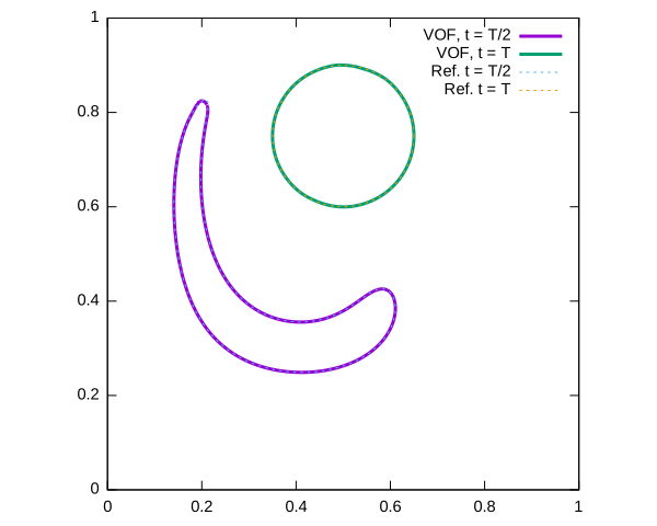
reset
set size ratio -1
plot [0.:1.][0.:1.]'vortex_vof_128_8_1.dat' w l lw 3 t "VOF, t = T/2", \
  'vortex_vof_128_8_2.dat' w l lw 3 t "VOF, t = T", \
  '../vortex_ana_8_4.dat' w l dt 2 t "Ref. t = T/2", \
  '../vortex_ana_8_8.dat' w l dt 2 t "Ref. t = T"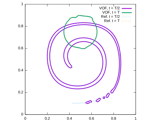
See also
References
| [rider1998] |
William J. Rider and Douglas B. Kothe. Reconstructing volume tracking. Journal of Computational Physics, 141:112–152, 1998. |