sandbox/jieyun/test/vortex_3d_ebit.c
3D deformation test with the EBIT method
The test, analogous to the 2D single voertex test, was first proposed by Enright, 2002.
A divergence-free velocity field
\left(u, v, w \right) = \cos(t / T)\left[ \begin{matrix} 2 \sin^2(\pi x) \sin(2\pi y) \sin(2\pi z) \\ -\sin(2\pi x) \sin^2(\pi y) \sin(2\pi z)\\ -\sin(2\pi x) \sin(2\pi y) \sin^2(\pi z) \end{matrix} \right]^T, \quad T = 3,
is imposed throught the domain, which combines deformation in the x-y plane with deformation in the x - z plane.
#define ADAPT 1

scalar f[];
scalar * interfaces = {f}, * tracers = NULL;

#include "grid/octree.h"
#include "advection-ebit.h"
event stability (i++) {} // this ensures that time step is computed before marker advection
#include "ebit-3d.h"

const char *OUTNAME = "vortex";
int level = 6, maxlvl, minlvl;
double Cfl = 0.125 [0], R = 0.15, xcenter, ycenter, zcenter, \
  ddt = 1. [0,1], EndT = 1. [0,1];
int IT;
double vol_ave = 0. [3];

int main(int argc, char * argv[]) {
  if (argc > 1)
    level = atoi (argv[1]);
  maxlvl = level;
  minlvl = max(level - 4, 2);

  init_grid (1 << level);

  ddt = Cfl/N *1. [0,1];

  xcenter = 0.35;
  ycenter = 0.35;
  zcenter = 0.35;

  EndT = 3.;

  IT = (int) EndT/ddt;

  run();
}

event init (i = 0) {
  vertex scalar phi[];
  foreach_vertex() {
    phi[] = sq(R) - (sq(x - xcenter) + sq(y - ycenter) + sq(z - zcenter));
  }

  init_markers (phi);

  semu2vof();
  volume0 = volume;
  vol_ave = 0.;
}
The timestep dt and the velocity field are set.
event stability (i++, i < IT, first) {
  double u0 = 1. [1,-1];
  dt = dtnext (ddt);

  double cost = cos(pi*tTime/EndT)*u0;
  foreach() {
    double xx = x/L0, yy = y/L0, zz = z/L0;
    u.x[] = 2.*cost*sq(sin(xx*pi))*sin(2.*yy*pi)*sin(2.*zz*pi);
    u.y[] = -cost*sin(2.*xx*pi)*sq(sin(yy*pi))*sin(2.*zz*pi);
    u.z[] = -cost*sin(2.*xx*pi)*sin(2.*yy*pi)*sq(sin(zz*pi));
  }

  boundary ((scalar *){u});
  tTime += dt;
}

#if ADAPT
event adapt (i++) {
  adapt_wavelet ({mask_intf}, (double[]) {0.02}, maxlevel = maxlvl, minlevel = minlvl);
}
#endif
Output the interface segments for visualization, as well as the time history of the volume fraction to a reference file.
Use the python script to generate a Tecplot file for visulizing the interface as triangular elements.
event interface_out (i++, last) {
  // if (2*(i + 1) % (int) max(IT, 1) == 0){
  //   int ii = 2*(i + 1)/max(IT, 1);
  //   char name[80], name_fem[80], name_con[80];

  //   sprintf (name, "%s%s_%d_%d_%d.dat", OUTPUTPATH, "vortex_3d_ebit", N, (int) EndT, ii);
  //   sprintf (name_fem, "%s%s_%d_%d_%d_fem.dat", OUTPUTPATH, "vortex_3d_ebit", N, (int) EndT, ii);
  //   sprintf (name_con, "%s%s_%d_%d_%d_con.dat", OUTPUTPATH, "vortex_3d_ebit", N, (int) EndT, ii);

  //   output_facets_semushin (name);
  //   output_facets_semushin (name_fem, tri = true, file_con = name_con);
  // }

  fprintf (stderr, "%.8e %.12e %.12e %.12e\n", (i + 1)*dt, volume, volume_int,
    (volume - volume0)/volume0);
  vol_ave += fabs(volume - volume0)/IT;
}
We compute the time-averaged mass error
E_\text{mass} = \frac{\int_0 ^{T}|V(t) - V(0)| dt}{V(0)} = \frac{\sum_{j=1}^{N_t} \left| \sum_{i=1}^{N_\text{cell}} \left[ C_i(t_j) - C_i(0) \right] \right|}{N_{t}\sum_{i=1} ^{N_\text{cell}} C_i(0)},
and the shape error
E_\text{shape} = \frac{\sum_{i=1}^{N_\text{cell}} \left| C_i(T) - C_i(0)\right|} {\sum_{i=1}^{N_\text{cell}} C_i(0)}.
event calc_infty_norm (t = end) {
  // This event is correct only if there is no markers on the computational boundary
  #if ADAPT
  refine (fabs(x - xcenter) <= 0.25*L0 && fabs(y - ycenter) <= 0.25*L0
  && fabs(z - zcenter) <= 0.25*L0 && level < maxlvl);
  #endif

  // Initial shape
  vertex scalar phi[];
  scalar f0[];
  foreach()
    f0[] = f[];

  foreach_vertex() {
    phi[] = sq(R) - (sq(x - xcenter) + sq(y - ycenter) + sq(z - zcenter));
  }

  init_markers (phi);
  semu2vof();

  foreach()
    swap(double, f[], f0[]);

  double v0 = 0., v1 = 0., delta_v = 0.;
  foreach(reduction(+:v0) reduction(+:v1) reduction(+:delta_v)) {
    v0 += f0[]*dv();
    v1 += f[]*dv();
    delta_v += fabs(f[] - f0[])*dv();
  }
  if (pid() == 0) {
    printf ("Volume:t0: %e T: %e\n", v0, v1);
    printf ("E_m Error: %.8e, E_g Error: %.8e\n", fabs(v0 - v1)/v0, delta_v/v0);
    printf ("Time-averaged mass Error: %.8e\n", vol_ave/v0);
  }
}
Results
Time history of the mass error: E_m (t) = \left( V(t) - V(0) \right) / V(0).
reset
set xlabel 't'
set ylabel 'E_m'
plot 'log' u 1:4 w l lw 3 t 'EBIT'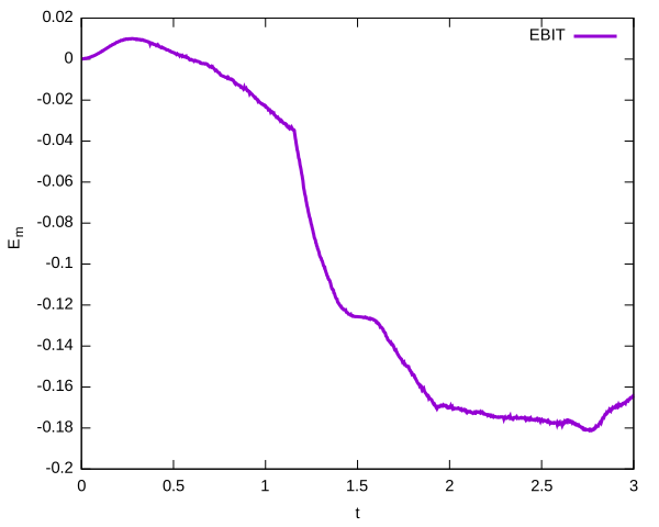
References
| [enright2002] |
Douglas Enright, Ronald Fedkiw, Joel Ferziger, and Ian Mitchell. A hybrid particle level set method for improved interface capturing. Journal of Computational Physics, 183:83–116, 2002. [ DOI ] |