sandbox/jieyun/test/stagnation_ebit.c
Stagnation flow
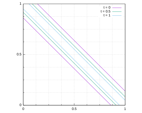
Two parallel linear interfaces oriented at 45 degrees are placed inside a flow field (u, v) = (0.5 - y, 0.5 - x) with a stagnation point at (0.5, 0.5). We use this test to demonstrate the capability of the EBIT method to preserved the sub-cell thin film.
#define LEVEL 3

scalar f[];
scalar * interfaces = {f}, * tracers = NULL;

#include "advection-ebit.h"
event stability (i++) {} // this ensures that time step is computed before marker advection
#include "ebit-2d.h"

const double Cfl = 0.125 [0];
const char *testName = TEST;
x0: stagnation point, theta_0: rotation angle around stagnation point, d_film: initial thickness of film
coord xo = {0.5, 0.5};
double theta_0 = 45., d_film = 0.2;
double ddt;
int IT = 64;
Linear extrapolation is used to set the velocity in ghost cells to the exact value.
u.x[left] = 2.*u.x[] - u.x[1];
u.y[left] = 2.*u.y[] - u.y[1];

u.x[right] = 2.*u.x[] - u.x[-1];
u.y[right] = 2.*u.y[] - u.y[-1];

u.x[top] = 2.*u.x[] - u.x[0, -1];
u.y[top] = 2.*u.y[] - u.y[0, -1];

u.x[bottom] = 2.*u.x[] - u.x[0, 1];
u.y[bottom] = 2.*u.y[] - u.y[0, 1];

int main() {
  init_grid (1 << LEVEL);
  ddt = 1. [0, 1]*Cfl/N;
  IT = (int) N/Cfl;
  run();
}


event init (i = 0) {
  vertex scalar phi[];
  double cth, sth;
  cth = cos(theta_0/180.*pi);
  sth = sin(theta_0/180.*pi);

  foreach_vertex() {
    coord xp;
    xp.x = (x - xo.x)*cth - (y - xo.y)*sth;
    xp.y = (x - xo.x)*sth + (y - xo.y)*cth;

    phi[] = intersection(0.5*d_film - xp.y, xp.y + 0.5*d_film);
  }

  init_markers (phi);

  boundary ((scalar *){s});
  semu2vof();
  area0 = area;
}
The timestep dt and the velocity field are set.
event stability (i++, i < IT, first) {
  dt = dtnext (ddt);
  double cth, sth;
  cth = cos(theta_0/180.*pi);
  sth = sin(theta_0/180.*pi);
  foreach() {
    coord xp, up;
    xp.x = (x - xo.x)*cth - (y - xo.y)*sth;
    xp.y = (x - xo.x)*sth + (y - xo.y)*cth;
    up.x = 1. [0, -1]*xp.x;
    up.y = -1. [0, -1]*xp.y;
    u.x[] = (up.x + up.y)/sqrt(2.);
    u.y[] = (up.y - up.x)/sqrt(2.);
  }

  tTime += dt;
}


event interface_out (i++, last) {
  if (2*(i + 1) % (int) max(IT, 1) == 0 || i == 0) {
    int ii = 2*(i + 1)/max(IT, 1);
    char name[80];

    sprintf (name, "stagnation_%d_%d.dat", N, ii);
    output_facets_ebit (name);

    // reference file
    output_facets_ebit ("", stderr);
  }
}
Results
The shapes of the interface at t = 0, 0.5, 1. are displayed below. At t = 0, there is no sub-cell thin film. Sub-cell film is observed and preserved at t = 0.5, 1
reset
set size ratio -1
set xtics nomirror
set ytics nomirror
set xtics 0.5
set ytics 0.5
set mxtics 4
set mytics 4
set grid xtics
set grid ytics
set grid mxtics
set grid mytics
set style line 81 lt 0 lc rgb "#808080" lw 0.5
set grid back ls 81
plot [0.:1.][0.:1.]'stagnation_8_0.dat' w l t "t = 0", \
  'stagnation_8_1.dat' w l t "t = 0.5", \
  'stagnation_8_2.dat' w l t "t = 1"